
Cloud this and cloud that . . . Just kidding, but you should check out the New Vertical Profile Optimization on the Cloud with Civil 3D! Think about this:
The geometric design of a road is a crucial part in any highway construction project. Once fixed, the design determines largely the construction costs.
An optimal vertical road profile, with respect to earthwork cost, follows the ground surface as close as possible. The closer the road is to the ground profile, the fewer earthwork needs to be done in order to cut or fill sections of the road. However, due to design constraints like slope, grade changes, vertical curve length, etc., it is not always possible to follow the ground surface. Finding the road profile that minimizes the construction costs subject to design constraints is a process that we call profile design optimization. Traditionally, the design of road profiles is done manually by engineers using a
mass-diagram. In this approach, the vertical profile is evaluated with an integration of the earthwork volumes between the road profile and the ground surface.
The integral can be plotted by hand or with the help of software. After visual inspection of the mass diagram, the engineer changes the profile and re-computes the volumes. This process is repeated until a satisfying solution is found.
There are several disadvantages using the mass-diagram approach:
- The mass diagram does not provide a real cost for a given design.
- The mass diagram considers uni-directional earthwork only. It does not account for earthwork that could start on either end of the road.
- The mass diagram does not account for different costs, such as excavation, embankment, load, borrow, and waste.
- The mass diagram cannot combine multiple surface layers in combination with cut and fills.
- The mass-diagram approach is a manual approach that is not able to incorporate design constraints automatically.
- Due to timely and budgetary constraints, a final alignment is often chosen from a small selection of possible solutions.
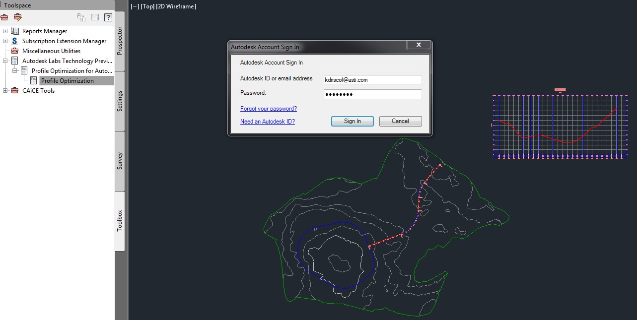
In the cloud-based vertical profile optimization, they address all the above shortcomings of the mass diagram with a new Cloud-based algorithm. To access this service, the user needs to use the Profile Optimization Wizard, which comes as a Civil 3D extension. Lets take a look.....
First we need to provide at least one EG centerline......

The design speed will be taken in the unit of the Civil 3D drawing (mph or km/h). Design speeds will be rounded on the server side to multiples of 5 when mph, or multiple of 10 when km/h. The server side optimization uses AASHTO 2001 design guidelines for the given design speed. Some of the design constraints can be overridden.


Holy Snap.....Results!


Kenneth L. Driscol
No comments:
Post a Comment
Note: Only a member of this blog may post a comment.