
August 4, 2015
Mark your calendars!
Mark your calendars! Applied Software is hosting a webcast on Aug 20 that is entitled “Do you need more Plant 3D piping supports?” In this webcast, I will be showing some of the additional supports we have created via Python Scripting for various clients and why you need to stop stick-building auxiliary steel supports and using non-intelligent and non-parametric 3D blocks of hangers and guides just like they did. This is not a session on how to create Python Scripts on your own but more of what all goes into the work that Applied Software can do FOR you! Feel free to register at

April 16, 2015
Inventor 2016 Improvements!
I have been looking for the new items in Inventor Professional 2016 and found some really great enhancements! These come from the "What's New in 2016" but if you don't have it loaded yet, you may not have seen these. This is not all of the enhancements either, but these are the ones that made me want to check it out further.
Copy Parameters to User
Parameters
While working with Parameters, you can now
copy an existing parameter, including all its settings and multivalues, as a
User Parameter. Previously, recreation and manual entry was required for each
value.
Import and Export External Rules Configuration for iLogic (not available in Inventor LT)
You can
now import/export iLogic configuration settings (as an XML file) to be shared
between different users and machines. Once configured, externally mapped
folders appear beneath a Standards Directory tree that will update/refresh
immediately when content changes (sub folders and rules). In the past, external
paths had to be manually added.
External
rules configuration settings can also be leveraged and mapped during creation
of deployments.
Global
forms can now be refreshed through a right-click context option to reflect the
most up-to-date form.
Redesigned Format Text Dialog Box
The
Format Text dialog box is simplified and refined to be clear and easy to use.
Size of the dialog box is reduced to provide more space for editing in the
graphic window.
Text Preview in the Graphic Window
Text in a
drawing file is dynamically previewed in the graphic window when you create or
edit it. You can refine the appearance of text before you close the Format Text
dialog box.
In-Canvas Text Rotation
Select a
text object, and drag the blue rotation grip point to rotate text to the
desired position.
Sheet Metal Multi-body
The multi-body part environment
is extended to include sheet metal parts. You can now use a top-down workflow
to create multi-body sheet metal parts. Use the Make Components or Make Part
command and then open the derived components to create flat patterns for each
part in a multi-body part file.
Thickness Detection (yes!)
When you
convert a part to sheet metal, you are now prompted to select a base face. This
pick allows Inventor to measure the material thickness for you. After you
select a face, the Sheet Metal Defaults dialog box appears. The measured
thickness is displayed in the Thickness value box. Click OK to accept the
measured thickness value.
Convert to Freeform
Use the
Convert command to copy solid body or surface faces to the freeform
environment. Use the freeform edit tools to manipulate the shape.
Create Tangent Dimensions Between Circular or Arc Geometry Within a 2D Sketch
You can
now create tangent dimensions between circular or arc geometry within a 2D
sketch. This workflow will allow you to fully constrain a circle using tangent
dimensions instead of a traditional diameter dimension, or the use of the
center point of the circle.
The Show/Hide All Constraints Display Setting Persists (yes!)
The
selected Show All or Hide All Constraints display setting remains active as you
sketch and throughout your editing session. Previously the show or hide setting
did not persist when you created new geometry or when you started a new sketch.
Large Assembly Performance
The Disable Automatic Refinement
option is added to the Application Options, Display tab. Disabling automatic
refinement provides a coarser model display and improves graphics performance
in large assemblies such as when changing a level of detail. Coarse faceting is
used until you select the Refine Appearance command in the View tab.
Assembly Pattern (yes!)
The Midplane option is added to
the assembly Pattern command. Select the Midplane option to create a pattern
distributed on both sides of the original component.
Fast Drawing Creation
A new
Create Drawing View command merges several steps to one, so you can quickly
create drawing views from a model file. In the model file, arrange the model as
desired. Then right-click the root component in the browser, and click Create
Drawing View.
The
following model properties are automatically propagated from the model to the
drawing:
·
All active representations (design view, position, and level of
detail representation)
·
Current camera including Orthogonal/Perspective setting
·
Active iPart/iAssembly member
Centralized External Sketch Symbol Library Features
You can
now easily access and share your collection of sketch symbols through a new
external Sketch Symbol Library. This library is an Inventor drawing file that,
by default, is located in a subfolder of the Design Data location of your
project.
Work Features Can Now Be Projected Into a View Sketch (this is in the DWG)
You can
now create a view sketch on a model with included work features and select
those work features with the Project Geometry command. This capability in a
drawing view sketch allows you to reference, constrain, or annotate other
sketch geometry to projected work features that were included in the view.
Hidden Line Views for Standard Fasteners
A new
option is available to exclude all standard fasteners from hidden line views.
Model Orientation in Base Views (this is good!)
When you create a base view, View
Cube is displayed next to the upper right corner of the base view. Click a View
Cube face, edge, or corner, or click the rotation manipulators to set the
desired orientation of the model.
Revised Drawing View Dialog Box (this is much better!)
The
Drawing View dialog box is streamlined to support new workflows with direct
interaction in the graphic window.
Projected Views
Use the
direct interaction tools to create multiple projected views with the Base View
command, and to place projected views in the drawing.
To create
an orthographic or isometric projected view, click a triangular icon on the
base view border. The projected view is placed in a default location.
Align To Edge Option
A new To
Edge option is available to align balloons. You can select any linear edge on
the drawing sheet to specify direction of the aligned balloons.
Increased Performance When Opening Files from Other CAD Systems
Multithread
support is enabled. Multithreading allows Inventor to use multiple processors
if the hardware you are using contains a multi-core processor. As a result,
performance is increased when working on files from other CAD systems.
October 17, 2014
Plant 3D and Autodesk ReCap
If you are not using ReCap to register, index and manipulate your point clouds and then dropping them in AutoCAD Plant 3D to do as-built designs, you are missing out!

Come to Autodesk University in Las Vegas this year and attend my class on this very subject.
PD6092 - Simplify As-Built Modifications in Plant 3D: Autodesk ReCap and AutoCAD Plant 3D - 12/3/14 (Wednesday) 4:30 PM
Scott Hallmark
| ||||
October 16, 2014
Odds and Ends – A variety of things I have found for 2015

While I have had good experiences over all with the Autodesk
2015 products, as with any software there were fixes along the way. Here are my discoveries of some of those
obscure and maybe not so obscure.

1)
AutoCAD 2015 Cursor trails: Moving your cursor along would leave pixels
everywhere. Turning off Hardware Acceleration
would clear up the problem. Install the
Service Pack and you can turn Hardware Acceleration back on.

2)
Plant 3D 2015 Extension 1: The Plant developers
are not waiting on new releases to give more functions in P3D. However, the Extension 1 was not compatible
with AutoCAD Service Pack 2. You cannot
even install the SP2 for a particular vertical, such as AutoCAD MEP, without it
affecting P3D. But, there is a fix that
fixes the fix that broke the Extension 1.
After installing any AutoCAD 2015 SP2, run the .BAT file.

3)
AutoCAD Electrical 2015: The error could come
with several messages. The main one I
have seen is: Unhandled Exception
C06D007E(Delayload “acewstr.dll” Module Not Found) at address FCFA940Dh. Just running a Repair or Reinstall will not help. The fix is to uninstall the Microsoft Access
database engine 2010 and reinstall from the install path, and may be a
variation depending on install method:
…\...\Autodesk AutoCAD Electrical 2015\3rdParty\AceDataEngine\x64\AceRedist.msi.

4)
Recap 2015: Will not open a .FLS file
format: While the File of Type shows it,
an error will keep coming up that says it isn’t a supported file type or is
corrupted. You will need to install the
Faro Scene 5.3 SDKs and register new DLLs.
This is done all manually, in that there is no MSI to run to fix it up.

5)
Multiple Suites Install: Most of you probably will not run into this,
but in my world it is standard business to need to install multiple
suites. If Factory Design Suite is one
of yours, install it first. When you
install it, the Application Manager will want to update a lot of the
applications. Don’t do it until you are
finished with the other suites. I have
found that, for example, reinstalling a suite or the subsequent suite install
will want to install the BIM360. But if
it is already upgraded, the install will message that a newer version is
already installed and then close out, without installing the applications
needed. The fix if this happens, is to
go back and uninstall all the BIM360s.
Reference Links:
#2: http://forums.autodesk.com/t5/autocad-plant-3d-general/autocad-plant-3d-2015-extension-1-now-released/m-p/5281605/highlight/true#M15655
#2 The BAT file can be found: http://docs.autodesk.com/PLNT3D/2015/ENU/readme.html
#3: http://knowledge.autodesk.com/search-result/caas/sfdcarticles/sfdcarticles/Error-The-driver-AceRedist-is-missing.html?v=2015
#4 Directions are covered: http://www.laserscanningforum.com/forum/viewtopic.php?f=49&t=7140
dennis
#2: http://forums.autodesk.com/t5/autocad-plant-3d-general/autocad-plant-3d-2015-extension-1-now-released/m-p/5281605/highlight/true#M15655
#2 The BAT file can be found: http://docs.autodesk.com/PLNT3D/2015/ENU/readme.html
#3: http://knowledge.autodesk.com/search-result/caas/sfdcarticles/sfdcarticles/Error-The-driver-AceRedist-is-missing.html?v=2015
#4 Directions are covered: http://www.laserscanningforum.com/forum/viewtopic.php?f=49&t=7140
April 17, 2014
What's New in Autodesk® AutoCAD® Civil 3D® 2015?! Here's the scoop!
Wondering what the new features are in the recently released Autodesk® AutoCAD® Civil 3D® 2015?
Read on for a comprehensive review brought to you by Autodesk! As a Autodesk Platinum Partner, we want to share this great piece of information with you and please don't hesitate to contact us if you have any questions.
Corridor modeling enhancements
Experience greater flexibility when designing and displaying corridor models.
- Corridor frequency (target and baseline)
- Corridor sampling improvements
- Retain corridor targets when substituting a sub-assembly
Profile layout enhancements
Experience greater efficiency when creating profiles.
- Extend curves and tangents to profile extents
- Create Free curve using Pass Through point
- Change Parameter Constraint (selected curve)
- New “Profile Locking” controls and display notifications for impacted Vertical Alignment entities if Horizontal Alignment changes
Production drafting enhancements
Create production deliverables more efficiently.
- Re-associate various Surface and Alignment labels to different Civil 3D source objects
- Stagger “Corridor Point” section labels
User Interface
Work more efficiently on daily tasks.
- Improved consistency between the AutoCAD Civil 3D and AutoCAD ribbon / command set.
- Improved graphics, enhanced visual feedback and object selection.
Subassembly Composer
Build custom subassemblies more easily. Improvements include support for “Voids” in shapes, Axis of Rotation, and Rail Cant.
Geographic Location (Online Map Data)
Geographic Location functionality is significantly streamlined and enhanced including a new capability to capture and embed Online Map Data (e.g., aerial map information) for offline viewing and plotting.
Reality Capture
Improved performance and more flexibility when working with point cloud files.
Interoperability and Data Exchange
Help improve collaboration with new and enhanced functionality.
- Enhanced export capabilities for DWG™ and DGN
- Export Civil 3D model elements (corridor models, surfaces, alignments/profiles, and gravity and pressure pipes) and 3D solid AutoCAD modeling objects to Keyhole Markup Language (KML).
- Open and edit AutoCAD Civil 3D 2015 drawings in AutoCAD Civil 3D 2014 and 2013 software.
About Autodesk® AutoCAD® Civil 3D®
A civil engineering design and documentation solution that supports Building Information Modeling (BIM) workflows. Using AutoCAD Civil 3D, infrastructure professionals can better understand project performance and intent, improve and maintain more consistent data and processes, and respond faster to design changes, all within a familiar AutoCAD® environment.
Visit our online learning website: LiveLab Learning for more training information!
February 24, 2014
Plant 3D 2014 and Ortho folder setup
I have had many calls about this issue with Plant 3D 2014, so I thought I would go ahead and let everyone know the issue with creation of the Orthos folder when a Project Template is used. This issue seems to only show up after installing the Extensions (Extension 1 & Extension 2 are available via your Subscription website). The background: When creating a new Plant Project without a Project Template, all goes well. But, as soon as you point to a Project Template, you discover that Ortho creation doesn't work. Furthermore, in some cases, you get an endless loop of new drawings being created, affectionately referred to as being "spammed with new drawings".
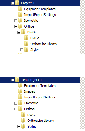 To the left shows what will happen with the folder
structure for Orthos, if the Project Template option is used and the standard
setting for Orthos/DWGs is selected. The
results of this folder structure will cause the Ortho creation to fail.
To the left shows what will happen with the folder
structure for Orthos, if the Project Template option is used and the standard
setting for Orthos/DWGs is selected. The
results of this folder structure will cause the Ortho creation to fail.

Within the Project Setup Wizard, Page 4 of 6, the standard setting for the Orthographic output directory: is ...\Orthos\DWGs as shown in the pic to the left.

Backspace out the DWGs folder so that the Orthographic
output directory points to Orthos\ folder as shown in the pic to the left.


So what happened and what should have happened?
To the left shows what will happen with the folder
structure for Orthos, if the Project Template option is used and the standard
setting for Orthos/DWGs is selected. The
results of this folder structure will cause the Ortho creation to fail.
Note the Orthos/DWGs folder
contains a duplicate of DWGs and then the Orthocube Library and Styles folders.
To the left shows the proper
folder structure for Orthos, and requires a change to the settings adopted from
a Project Template during creation of new project, and then a change
post-creation of a new project.
Note that the DWGs, Orthocube
Library and Styles folders are listed under Orthos/
Steps to insure proper new project creation for the Orthos
folder structure when using a Project Template.
Within the Project Setup Wizard, Page 4 of 6, the standard setting for the Orthographic output directory: is ...\Orthos\DWGs as shown in the pic to the left.
Continue on through the Project Setup Wizard, accepting the
default settings, but do not check the box on Page 6 of 6 to “Edit additional
project settings after creating project”. I have found that if I do check this box and make the needed change, it still messes up.
Leave the check box blank and allow the new project to be
created.
Once the new project has been created, it is now safe to make one last edit to the
Project Properties need to insure that Orthos will be generated
properly.
Note that now, as
was set in the Setup Wizard, the Ortho drawing output folder is set to the …\Orthos\
folder. The setting will need to have
the DWGs folder added.
Note the setting now for the Ortho output folder ends with the DWGs folder.
-dennis
January 14, 2014
Inventor 2014 Service Pack 1 and Update 2 of Service Pack 1
 As the title implies, there is a Service Pack 1 for Inventor 2014. After installing SP1, over time I began to see a pattern of problems, particularly with Content Center, in that it would just stop working and would lock up the application. Also, I found that if I renamed a file in a project, then launched Inventor, that new named file would have problems. I guess I wasn't the only one, because Autodesk released an Update 2 to Service Pack 1. Odd name, but basically a fix for what SP1 and Update 1 broke. The Update 2 to Service Pack 1 includes Update 1 so you will only need SP1 and Update 2. The link below will take you to the Update.
Update 2 to Service Pack 1
Subscribe to:
Posts (Atom)