Showing posts with label Civil 3D. Show all posts

May 10, 2012

BIM Coordinator

Autodesk Labs have a new product to assist with coordinating Revit with Civil 3D.  This new add-in tool will allow the coordinates inside of Civil 3D be saved out as an external file, that can be imported into Revit to acquire the Shared Coordinates.  This process appears to work without having to import the actual Civil file.  A quicker, simpler way to make sure you Revit model has the correct coordinates.


The add-in app is written for release 2012, but I copied it to my 2013 version and it appears to work correctly.

Check it out!


December 27, 2011

How to get CaiCE Project Data into Civil 3D

First of all, I had an client who wanted to get some Survey data, DTM models and Cross-Section data from CaiCE into Civil 3D......Nooooo Problem!  Solution - CAiCE Translator Extension for AutoCAD Civil 3D 2012. 

The CAiCE Translator Extension for AutoCAD Civil 3D 2012 is an application that converts data from CAiCE projects into Civil 3D. Project data including survey data, points and chains, horizontal and vertical alignments, surfaces and cross sections can be selected and imported into the current Civil 3D drawing file. The extension does not require CAiCE to be installed!

Under the Toolbox......


 Survey Points and Data


 DTM Options.......

WOW! Presto! Look in your Toolspace................

http://usa.autodesk.com/adsk/servlet/ps/dl/item?siteID=123112&id=17461535&linkID=9240698

Kenneth L. Driscol

December 23, 2011

Grading in the Daylight


Daylight Rounding; try it, you might like it! Old school engineers and drafters still live in a world when a set of plans is a work of art and should reflect the real world. However, in the modern computing world, when finite math reaches a number, the computing stops. A great example of this is how the contours look when you are creating a corridor surface.

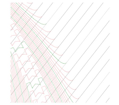
Contours are a major player in the older practice of hand drafting. Contours are flowing objects with few hard edges and angles in the real world. Yet when we calculate a TIN intersection, the contour will just stop and make an abrupt turn where that intersection is computed without any thought to what the end result will look like. I hear this question a lot from users: “How do I make my contours “tie in” with corridor surfaces?” By “tie-in,” they mean make the swooping arcs and look like they eventually will in real life. If you follow the link below, you’ll see an example of what old school engineers don’t want to see, how to fix it, and what the end result is.

In the image above you can see what happens when the corridor daylight subassembly calculates the intersection with the TIN and reaches true daylight: You’ll notice that the proposed contours (green and magenta) tie into the existing contours (gray) at a very harsh angle. This is typically not desirable to some engineers. Luckily, we can fake this in by setting a few parameters in the daylight subassembly. You’ll notice in the image below that I have set some rounding options in my subassembly parameters. I want a circular rounding, with a radial rounding, using a 200’ radius, and a tessellation factor of 10 (the highest factor.) And here are the results of these settings: You will notice that the contours are more “swoopy” (a term used by a not-so-old-school engineer I once worked with who actually preferred angular contours) and they tie in better. They really look more like they will in the real world once the project is built.You can play with the numbers and the options to get results that you want – the tessellation factor gives a more “rounded” look, and increasing the radius gives a more pronounced rounded tie-in. You can also experiment with the differences between parabolic and circular......
Kenneth Driscol

December 19, 2011

Explore Multiple Design Alternatives

AutoCAD Civil 3D enables you to explore multiple options, ultimately helping you produce an optimized design. The integration of imagery and geospatial data assists in identifying an optimal solution early in the overall process, helping to save time and money.

• Import geospatial data, such as soil types, land use information, and environmental constraints to more quickly analyze and better understand the probable impacts of different alternatives.

• Use imagery and terrain models from Google Earth™ mapping services and other sources to help visualize the ecosystem of a project.

• Most project data—such as survey information, surfaces, profiles, horizontal alignments, and
corridor models, as well as related annotations and labels—have predictable relationships with other elements in your design. This results in the dynamic updating of model elements when related elements are changed.

• AutoCAD Civil 3D includes terrain shaping tools that support large-surface models while
maintaining dynamic relationships to source data, including contours, break lines, corridor models, and grading objects.

• Use surfaces as references for creating profiles, sections, and corridors. Any changes to the source data result in automatic updates to surfaces and references, which helps you save time and reduce errors. This means that several alternatives can be evaluated quickly since immediate feedback is given, helping to ensure important design constraints are held, such as project limits staying within existing rights of
way.

Built-In Standards


Standards are the universal language of civil engineering. Almost all projects need to respect local constraints for steep slopes, pipe layout, minimum parcel size and road frontage, sight distances, road curvature, and more. Additionally, construction documents need to use the appropriate line types, line weights, and symbology to be readable for construction and accepted by regulating agencies. Designers can make changes with more confidence because AutoCAD Civil 3D 2012 software helps them to meet the design criteria mandated
by the customer and various third parties.


  • AutoCAD Civil 3D 2012 software has built-in tools that help reference and report violations of industry requirements, like AASHTO and TAC standards.
  • Corridor models can be built using assemblies with parametric constraints based on agency requirements.
  • Customize tables to help you adhere to unique standards that are enforced by local agencies.
  •  Maximize parcel yield and green space using built-in tools to help meet local standards for size, frontage, and setback. Use interactive editing tools to preview changes and refine layouts without your established constraints before deciding on a final design.
  • Autodesk Storm and Sanitary Analysis, included with Civil 3D, is based on industry-leading hydrologic models such as EPA SWMM Version 5, TR-20, TR-55, and other regional models, which facilitates submittal of stormwater management reports in many jurisdictions.

December 15, 2011

Integrate Design and Analysis


Teams regularly spend time recreating various aspects of the project design in separate analysis software. Different aspects of civil designs must be
analyzed at various stages of a civil project. The designer needs a good understanding of slopes, earthwork volumes, stormwater management, and more.  Analysis results must be considered as a whole in order to make design decisions  that satisfy the project requirements. Civil 3D helps eliminate redundancy in  your workflow by analyzing the model you’ve already built. Designers can get
feedback in real time, while there is still an opportunity to refine the design
and make changes.

• Analyze pre- and post development hydrologic conditions
using integrated hydraulic and hydrology tools.

• Analyze your AutoCAD Civil 3D pipe network models, culverts, and channels using Autodesk® Storm and Sanitary Analysis 2012 software to help make design decisions. Automate the
generation of robust reports for submittal to review agencies.

• The mass haul and earthwork features enable contractors and engineers to more effectively
plan the movements, amounts, and placements of material during construction. As
designs are changed, Civil 3D can help to quickly analyze earthwork balance
points, determine the amount and direction of material to be moved, and identify
optimal locations for borrow pits and dump sites.

• Directly import customized pay item information into AutoCAD Civil 3D 2012 software for use in
assigning pay item values to objects in the drawing, including AutoCAD entities
and AutoCAD Civil 3D model elements. Automatically calculate quantities and
generate reports based on pay item values.

Kenneth Driscol

December 5, 2011

Creating pipe Networks from GIS Data Part 1

 This is the first post of a three post series in which I will be covering pipe networks created from GIS data. Using this feature new to 2012 you may have noticed that GIS data in the form of SHP files may not always be what you expect. Especially when you import this data and create pipe networks from it, remember - garbage in, garbage out.

If the original GIS data has the correct object data associated with it, (inverts, pipe size, materials, etc.) the better end result you are going to get. Additionally, you will need to take into consideration the amount of vertices that these pipe lines have in them. If the pipes have many vertices between actual pipe start and end, Civil 3D will place a null structure at each one of these vertices. This may be acceptable if the pipe really does end there, but edits may need to be made prior to import as well as after the fact.  If the data has excessive amounts of vertices, you can easily edit these with a few different options.

First, you have the new AutoCAD functions in which you can hover over the vertex and it gives the option to remove the vertex. This is a quick and easy option if you only have a few vertices to address. Next, is the most efficient option; use the Map Cleanup functions of the MAPCLEAN command. The Simplify Objects option will make quick work of the extra vertices. This makes quick work of entire city blocks of pipe data that hase excessive amount of unnecessary vertices. Finally, you have the option of using the WEED command, which you may recall using with feature lines, but works with polylines as well. I found this to be the least ideal option, but it is definitely worth having available in case you need it. So prior to importing your SHP data as Civil 3D pipe networks, you should review the data you have obtained to ensure that all excess vertices have been addressed to avoid the excess null structures.

December 2, 2011

Civil 3D 2012 Service Pack 1

AutoCAD Civil 3D 2012 Update 1
In a continuing effort to provide high quality products, Autodesk has released AutoCAD Civil 3D 2012 Service Pack 1, which fixes or addresses a variety of issues discovered by customers and by Autodesk's internal testing team. This Service Pack includes all previous hotfixes for AutoCAD Civil 3D 2012. It also includes the fixes included in AutoCAD 2012 Service Pack 1 and AutoCAD Map 3D 2012 Service Pack 1. Note: This update applies to all language versions and to versions of AutoCAD Civil 3D 2012 with previous hotfixes applied. Before applying this update, make sure that any customizations made to the user profile (such as, customizations made to the support file search paths, print file customizations, printer support file paths, redirections, custom template settings, and so on) are exported to a secure location, then imported and reapplied after the update has been successfully installed. You cannot run an automatic uninstall to remove this update. To restore your version of AutoCAD Civil 3D 2012 to its pre-update state, uninstall AutoCAD Civil 3D 2012 and reinstall it. c3d2012_win32_sp1.exe (exe - 28421Kb)

November 8, 2011

The 12d Data Extension for AutoCAD® Civil 3D® 2012

Move forward with no worries, DOT......

The 12d Data Extension for Civil 3D 2012 enables data from 12d® Model™ software by 12d Solutions Pty Ltd to be imported and used within AutoCAD Civil 3D 2012 software.
The extension provides support for 12d Model ASCII files from all known
versions of 12d Model software up to and including Version 9.0.


Supported 12d Model data types include:

Alignments andprofiles
Super strings
Drainage strings
TIN’s
Text strings

November 7, 2011

The Volumes Dashboard Extension for AutoCAD® Civil 3D® 2012


Playing in the Dirt.........

The Volumes Dashboard Extension for AutoCAD Civil 3D 2012 software provides a streamlined interface for design and construction professionals to calculate, report and visualize surface volumes within AutoCAD Civil 3D 2012 software.
Refining earthworks through iterative design is a common operation that is
performed throughout the design and construction process on infrastructure
projects. This extension can streamline and help optimize the current process
in AutoCAD Civil 3D 2012; it will also provide an easy to follow workflow for
common tasks, helping new Civil 3D users become productive, more quickly.