December 10, 2012

Revit 2013 - New Features - Dia. Dims


Yes! Finailly... Diamater dimensions are in Revit!! From the dimensions panel | Annotate tab, choose the diameter dimension tool. Make your selection preferences in Type Properties on how you want the dimension to display. See above.

December 6, 2012

Revit 2013 - New Features - Project Browser

 
The Project Browser is now searchable by right clicking on it. Type in the name or partial name of a view or group of views yo uare looking for. Make quick work out of the little known searchable tool.

December 4, 2012

Revit 2013 - New Features - One Box


For Revit Suite users, take advantage of the “One Box” concept. Which includes multiple discipline tools and tempaltes. All the tools needed to work with Architecture, Structure and MEP come together in this release to expand your workflow.

November 19, 2012

Virtual AU


Don't Miss AU Virtual—It's Free

AU Virtual will deliver live streaming sessions from AU 2012 in Las Vegas, plus more than 250 on-demand technical classes on the newest releases of Autodesk products and classes on the latest trends and challenges facing the design industry—right to your desktop.
View the AU Virtual class catalog starting November 15, and then join your peers for this free online event, November 27-29, 2012. AU Virtual

November 16, 2012

Autodesk University 2012


Autodesk University is right around the corner.Traditionally it has been the week after Thanksgiving in Las Vegas. There is still time to register and be a part of the action! Autodesk University 2012

October 26, 2012

Special Characters in Revit Schedules


Is this a standard Revit schedule?


Revit does not allow for graphics to be included in a schedule.  This has been on the wish list but has not been included as of yet.  Revit does allow for special characters to be used.  Special characters can be used as long as the character is of the same font style as the font defined in the body font style of the schedule.  One example of the use of special characters would be to create a ‘dot matrix’ type of schedule where you want to show a special character as the dot.  

Learn how to create this type of schedule plus many other scheduling tips in my AU session.  

AB1712 - Schedules: Beyond the Basics
Wednesday 8:00-9:30

See you in Vegas!

October 23, 2012

Revit Sheet List - Linked Files

Client asked this question today. Can I link a file and see the sheets in the link file? The answer is no. But wait there's more.

A nice feature out of the box with Revit is the ability to create a Sheet List. What is a sheet list? A sheet list is a schedule of sheets in a project. It is also known as a drawing index or a sheet index.

Did you know you can include in your current file’s sheet list a list of sheets in any linked files? For example, while in your architectural model, you can include sheets from your linked structural model.

While you cannot see linked sheets, you can include them in your sheet list. Go to View Tab -> Create Panel -> Schedules button -> Sheet List. Make sure to place a check in the “Include elements in the linked file” check box. That’s it!

October 17, 2012

Revit Stair By Component (and Sketch too?)

Have you tried Revit 2013 Stair by Component yet? If you haven’t, you don’t know what you are missing! So you can either model stairs by component or you can model stairs by sketch. Right? Actually, you can do both with the same stair! If you need to model stairs, start with Revit 2013 new Stair by Component. But what if you need a custom landing? Easy, let Revit create the landing and then modify it. Select the landing and go to the ribbon. Select Convert tool in the “Create Stair” tab and “Tools” panel. A message will notify you converting the landing to sketch-based is irreversible. No worries, select the Close button and keep moving forward. Next, select the “Edit Sketch” tool in the ribbon and you can modify the landing boundary. Select the green check mark to finish edit mode for the landing. Select the green check mark again to finish creating the stair. There are many other reasons for using Stairs by Components.  This is just one small tip.


September 28, 2012

Revit LT is not AutoCAD LT

Those of us who remember when AutoCAD LT was first released remember our initial reaction. It was cheap and it did almost everything AutoCAD did. Right? Well, we soon discovered that AutoCAD LT was lacking more than we wanted. It was still a great product but power users were missing the power of AutoCAD.
Revit LT on the other hand is a very powerful version of Revit. Yes it does have limitations but it's limitation do not hamper small companies. The biggest difference with Revit LT is that it does not allow you to do worksharing; that means multiple people can not work on one project at the same time. If you are a small firm and designers do not need work sharing, then Revit LT will do everything you need Revit to do.
If you have not made the switch to Revit and you are a small firm, you should consider Revit LT. Speak with a Sales Account Manager and Senior Application Specialist to see if Revit LT is for you.  Check out this link, http://usa.autodesk.com/revitlt/.

September 24, 2012

Navisworks 2013 Update 2 is now available.

http://usa.autodesk.com/adsk/servlet/ps/dl/item?siteID=123112&id=20458011&linkID=10382102

The Navisworks 2013 Update 2 readme cites several buggy features being fixed, primarily around crashing issues.  Alas though, still no fix for the READER portion of RMEP files where it brings in the pipe fittings as single-line.

I discovered something great!  SP2 must of fixed one major issue with the Clash Detective.  Now, when you write the Report = Viewpoints, the Viewpoints created 'remember' how you viewed it in the Results Tab, what is on, what is off, Dim settings, etc...wonderful.

Important HotFix to preserve Markups on the Results Viewpoints:
http://usa.autodesk.com/adsk/servlet/ps/dl/item?id=20626807&siteID=123112&linkID=10382102

August 27, 2012

Autodesk 360 Mobile

Autodesk introduced last week a mobile version of their popular Autodesk 360 website and tools.
 
Autodesk® 360 Mobile brings the convenience of Autodesk® 360 to your iOS devices.

Design Review Mobile has gotten a makeover, featuring additional functionality and a new name, Autodesk 360 Mobile.

Autodesk 360 Mobile helps you expedite the design process by viewing and collaborating on files in the field, directly on your iPad, iPhone or iPod touch. View and annotate drawings on the spot, reduce the need to carry around over-sized paper drawings, and enjoy an all-digital review workflow.

•Open and view files stored in your Autodesk 360 account
- 2D and 3D DWG™ and DWF™ files
- Revit® and Navisworks® files
•Use multi-touch to zoom, pan, and rotate drawings
•View meta data and other details about elements within your drawing
•Find tools that help you communicate changes with your collaborators

 
available via Apple or Droid
 
Autodesk 360 Mobile

July 30, 2012

Revit: Links Non-Selectable


One particular wish-list item for Revit has been a Pin feature that also will not allow the users to select what has been pinned.  While this wish-list feature may (or may not) show up within Revit in the future, a procedure using Design Options can be used today.  Using this method, you will be able to see the linked model, still be able to use it for Space placement and hosting Face-based objects, but you will not be able to select it.
 

Steps Involved:
  1. Before selecting the Insert RVT command, setup the Design Options:
    1. Create the first Design Option Set which will also create one Option (primary).  You will only want the one Option in this Option Set
    2. Rename the Design Option Set with a name that is descriptive, such as Revit Model Links
    3. Rename the one Option of the Set to something like: All RVT Links
  2. Now set as active the Design Option: All RVT Links
  3. Insert the RVT link and Pin in place
  4. Set the Type Properties of the link to Room Bounding
  5. Set the active Option back to Main Model
  6. The linked model now should be visible but not selectable.
  7. Should you need to select the link now, you will need to change the active Design Option back to the All RVT Links option.  Just don’t forget to change it back to Main Model prior to adding in any MEP layouts or objects.
NOTE: Now in your Visibility Graphics dialog, you will have a Design Options tab.

dennis

Revit Railings - How to move the handrail

You can create 3D stairs and railings using Revit Architecture. But how do you change the height of the handrail? The most obvious answer is to select the railing (System Family: Railing) and go to type properties. You will see a Height type parameter under Handrail 1 set to 3'-0" but it is a read-only value. Read-only? Now what?
If you want to adjust the height of your handrail, you must select the handrail (System Family: Handrail Type) and not the railing. How do you that? Easy, simply hover over the handrail and use the TAB key to highlight the handrail and then left click to select just the handrail. Now go to type properties for the handrail and change the Height type parameter to 2'-10" or whatever height you want!

July 26, 2012

Revit Conceptual Modeler

The Revit Conceptual modeler, also know as the Building Maker, is a set of tools within Revit to assist you with designing a building. Whether it is figuring out a free-form shape, or how a building will sit on a site, these tools are very useful in accomplishing those goals. Here is a 10 minute video we put together showing the Revit Conceptual modeler. After clicking play, you may want to maximize the window to see things better...


July 25, 2012

Section Marks in Revit Disappear


Oh No, My Section Marks in Revit Have Disappeared!?
This particular dilemma crops up occasionally. Did some or all section view tags disappear when you changed the scale of the view? Fear not, it is probably not a problem with your view, project or Revit. It is a parameter associated with the section view. When you place a section in a view, it assumes the scale of the view. It also sets the “Hide at scales coarser than” parameter to the same scale. That means if you place sections in a view, then change the scale of that view to be greater than what was originally set to (i.e. your view was set to 1/8”=1’-0” and you change it to 3/32”=1’-0”), your section view tags will disappear. This is a default behavior of section views. To fix this you open the section view, go to the Properties PaletteèHide at scales coarser than parameter and change to allow the section view tags to show at larger scales. This setting is intended to help control the display of section view tags. Sometimes we forget this setting is there until they disappear.

July 23, 2012

Revit MEP 2013 – Selection Sets

Selection Sets:
The capability to create Selection Set Filters has been a part of the Revit Structural for some time now.  With the release of RMEP 2013, the building engineers now have the same capability.  With this feature, a selection set of objects can have display settings applied in the Visibility Graphics just like we have done with Filters setup based on Filter Rules.  Have you ever needed to turn off several objects in a view, but didn’t want to turn off all the objects of the same category?  Have you ever wanted to color certain objects differently from the category?  Then Selection Sets may be your answer.


In the view to the left, I have a water closet and a vanity sink unplumbed that I do not want to show.


When I select the two fixtures, on the Modify ribbon panel, you will find now, the Selection Panel which contains the feature to Create and Edit Selection Sets.  (Yes, you are seeing that right, I use magenta as my selection highlight color.)


I will give my selection set a name: MySelectionSet


Next, we go to the Visibility Graphics/Add Filters and you will see that the created selection set, MySelectionSet, is available to add to the Filters of the view.


Once added, our selection set has all the filter options to turn off the visibility, control surface coloring, transparency and halftone.

Benefits:As opposed to “Hide in View”, the Selection Set can easily be made visible without digging through “Reveal Hidden Elements”.  The selection set filter can be used again and again in any view.  Also, in my example I worked with just the category Plumbing Fixtures, but I could have just as easily selected objects from multiple family categories.


For an overview of the new features and enhancements for Revit MEP 2013, see the link:http://usa.autodesk.com/revit/mep-engineering-software/#whats_new
dennis

July 16, 2012

Visualizing Revit MEP Spaces in 3D

I am very visually oriented.  I like to see what I am modelling.  However, when it comes to Spaces within RMEP, you couldn't see what you are really doing. While there is a model view of Spaces within the built-in analysis interface, I still had difficulty exploring to see where I may have missed placing Spaces or where Spaces were overlapping one another. Now, working between RMEP and Navisworks, the Space model can be visualized.  Start with the settings for Revit NW Exporter and/or NW Reader:


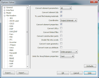
Navisworks Option Editor for Revit File Reader  

Findings as I was exploring this feature:  You do not need to check the box “Convert room geometry” which is to convert the Spaces to construction parts.  Either way, the Spaces show up.  If using the NW Exporter from Revit, I still 
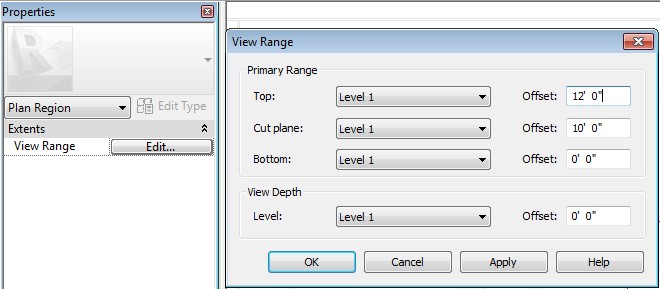
needed to have a 3D view as the active view when I issued the command.  If you have a Plan View up, example Level 1, then I found that my Level 1 Spaces came in flat/2D while Spaces from other floors were 3D.  You do absolutely have to Convert Entire Project.

I can see where this would help to insure all area volumes are accounted for with a Space. Look through the Space Model and find the gaps. Specifically where this helped me tremendously is in the Revit MEP Loads Analysis.  Reviewing the Spaces on the Detail tab, often you will get a warning about overlapping Space Volumes:
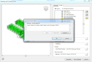
RMEP Loads Analysis
It can be difficult sometimes to find the overlapping.  Revit will not display the Spaces in a 3D view, which would help greatly to see and evaluate the Spaces overlapping, so using Navisworks becomes an important tool for visualization of the Spaces.
Below is a screen shot of how I setup my SearchSets and Appearance Profiler to make the Spaces easier to evaluate.

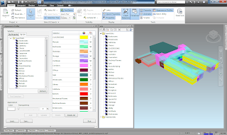
Navisworks Appearance Profiler
From here, I first tried to run a Clash Detective batch to find the overlapping Spaces, but discovered that the Spaces did not Clash with one another.  I even used the move to tool and move one Space clearly into another Space and then Clashed those two Spaces specifically, but still did not get a Result. I tried both normal Hard clash, and the new Hard(Conservative) clash (See some further notes on this below).


Then I discovered a magic setting, in the Rules tab, I clear the check mark for "Items in same group/block/cell".  Very odd, but nonetheless, I got a clash result.  Digging a little deeper, I found in Options/Model/Performance/On Load Collapse on Convert to be set to None.  Once I set this value, I was able to check the "Items in same group/block/cell" and still get clash.

Selected Spaces isolated by Hide Unselected
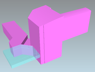
Now to analyze the Spaces' overlapping.  As I rotate around, I can see the problem easily:
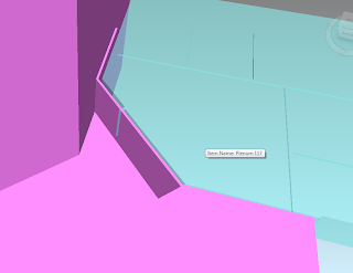
Slight overlap
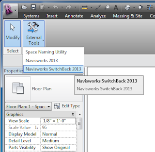
Head back into Revit MEP, put in a Space Separator, and my overlapping problem is gone.  If you haven't tried the SwitchBack function in Navisworks, now would be a good time to try it.  Note: you first have to have Revit open and Switchback turned-on:


A little more detail on the clashing: there is a new Clash Setting option called Hard(Conservative). The difference in the Hard(Conservative) and the standard Hard clashes is in how the defining triangles of an object are evaluated.  The normal Hard clashes look for intersecting triangles, while the Hard(Conservative) looks for intersecting space.  While this may not be the most accurate of mental pictures, think of it like this: picture clashing two pyramids.  Normal Hard will only show a clash when triangle of the two pyramids intersect.  Now, for Hard(Conservative) those pyramids' would be inside of a sphere (the sphere represents the pyramids' space), their three-points laying tangent on the wall of the sphere.  The Hard(Conservative) then would show a clash if the spheres clash.


dennis


July 3, 2012

Autodesk University 201


I am honored to have been selected to speak at Autodesk University for the 6th year in a row.  This year I will be presenting two sessions.
  • Schedules: Beyond the Basics
    • If you can model it, you can schedule it. Using schedules in Autodesk® Revit software is a powerful way of viewing the information in your Building Information Modeling (BIM) projects. Most users create basic schedules and have a good understanding of how to create schedules. What most users do not know is some of the more powerful features of schedules. This class will explore some of the lesser-known aspects of creating schedules, such as creating embedded schedules, using conditional formatting in schedules, and understanding key schedules. We will also dive into shared and project parameters and how to use them in calculated formulas.


    • Who Owns That - Best Practices for Coordinating All Disciplines
      • Let’s face it there are many elements in our Revit models that are re-modeled by the Architect, MEP and/or Structural Engineers. Who model it initially? Who owns it? Is Copy/Monitored being used? These types of questions should always be asked. Items such as columns, girds, ceilings, lights, plumbing fixtures, structural walls, floors, and roofs are usually populated in both the architectural model and the engineers’ models. This session will discuss the proper workflows between Architects and Engineers and how to model elements that have both architectural and engineering needs. Learn how to share the information of these elements without having to duplicate the geometry. . Sometimes knowing when and how to share elements will eliminate the need to have ownership of elements. Learning to create the proper workflow and families will ensure that collaboration is being achieved on your BIM projects.
    It is not too early to begin planning for this great event.  Registration opens September 5, 2012.  


    AU 2012 November 27-29

    June 25, 2012

    Navisworks 2013 Service Pack 1 Available

    Navisworks 2013 Service Pack 1:

    Time to update your 2013 Navisworks, see the link below.
    http://usa.autodesk.com/adsk/servlet/ps/dl/item?siteID=123112&id=19840757&linkID=10382102

    dennis

    May 21, 2012

    Inventor Simplification

    Autodesk Labs has released a new technology preview for Inventor 2013. The new add-in is called Inventor Simplification. If you are familiar with the Shrinkwrap tool that was released in Inventor 2010 then you will realize that this is just a more advanced version of Shrinkwrap. Inventor Simplification has made it easier to simplify parts and assemblies for downstream consumption by allowing you to remove intellectual property that might not be needed. Take a look at the videos and link below to get a better understanding on how amazing this tool really is.

    IP Removal

    BPM

    Follow the link below for the download and also for some additional information.

    -Jason Miles

    May 10, 2012

    BIM Coordinator

    Autodesk Labs have a new product to assist with coordinating Revit with Civil 3D.  This new add-in tool will allow the coordinates inside of Civil 3D be saved out as an external file, that can be imported into Revit to acquire the Shared Coordinates.  This process appears to work without having to import the actual Civil file.  A quicker, simpler way to make sure you Revit model has the correct coordinates.


    The add-in app is written for release 2012, but I copied it to my 2013 version and it appears to work correctly.

    Check it out!


    April 30, 2012

    3ds Max Design - MassFX


    Wind, gravity, and kinetics... we can incorporate all of these into a scene in 3ds Max Design. Lets start with a simple example of a bouncing ball, rolling down a sloped ramp, and the ball running into dominos that, once struck, will topple over, and make a series of dominos fall over, until it hits against a large domino at the end, that topples over.

    First we create a sphere, ramp and dominos and copying several of them to make a row to fall against. These are all made using standard creation tools of sphere for the ball, and box tools for the ramp and dominos.


    Next is to use the MassFX tools. These are tools which apply Rigid Body conditions to the objects. Allowing them to react and react to movement and collisions from other objects. The ball and dominos can all be applied as Dynamic Rigid Bodies. This make the an object that will not pass thru another object, but "bump" against them with some kind of reaction. For the object, especially the ball, we will enable gravity, so the ball can be dropped (no pun intended) and hit or react against the ramp, causing it to roll down to hit against the dominos, causing a chain reaction, knocking over each domino as it is hit.

    Watch this quick video on the ball dropping, rolling down the ramp and knocking over the dominos. Full screen will display the video better. Enjoy!


    April 26, 2012

    Navisworks 2013 – My First Impressions

    For an overview of the new features and enhancements for Navisworks 2013, see the link: http://usa.autodesk.com/navisworks/features/
    My Favorite New Feature
    Grids and Levels from Revit
    In the past we had to do a lot of setup to get grids and levels to display in Navisworks, particularly difficult to acquire from Revit.  3D Grids were introduced as a Family that helped to go from Revit to Navisworks.  Now in the new 2013, standard Grids and Levels will pass over to Navisworks.  The only specific setup that I have found to have this feature work: The grid must be native to the project; you cannot just have the grid displayed from a link.  Also, to get the Level information, you need to have at least one grid line.
    
    Revit Grids and Levels show up now in Navisworks 2013

    My First Bug Find

    Navisworks Revit File Reader
    With 2013 you can now read a RVT file just like you can read an AutoCAD DWG file.  Fortunately, the folks at Autodesk did not take away the Revit Plugin so that we can export from Revit to NWC.  I write ‘fortunately’ because I have discovered that the Reader doesn’t read some objects in Fine detail, while the Exporter does.  
    I tried the main two ways the Reader looks at a RVT file: Navisworks Named View and Whole Project.  My Navisworks Named View is set to Fine display.  
    With the Reader, Pipe and Conduit fittings are single-line.
    Cable Tray is Medium Detail level
    With the Exporter: Pipe, Conduit, Cable Tray and
    Duct all come in at Fine detail
    I have only tested RMEP objects and specifically just Duct, Pipe, Cable Tray and Conduit.  Duct seems to be OK either with the Reader or the Exporter, but I wonder if this is because Duct is the same when displayed in Medium detail as with Fine detail.  Cable Tray, in my test I used the Ladder type, the Reader brought it in equivalent to the Medium detail level, while the Exporter shows it as Fine.  Pipe/conduit fittings do show up with the Reader, but they are shown as the coarse/medium detail level, single-line display.  In contrast, the Exporter exports out the fittings as Fine detail (oddly though, the fittings come in NW a different color from the pipes themselves).
    Consequently, I recommend for you RMEP folks to continue using the Exporter until a fix gets applied in an Update.

    dennis

    April 5, 2012

    Mobility, Workflow and Productivity

    Mobility is an essential part of today’s normal business workflow. With the workplace no longer being defined by the company’s headquarter address, having immediate access to information – from the jobsite, the fabrication shop, on the road, at a client presentation – is crucial to successful business transactions.

    We put together a quick survey to explore how mobility is being addressed with technology in the design industry's day-to-day business. The survey can be accessed on our homepage at www.asti.com or here . Some preliminary results were included in our March webinar which focused on mobile apps.

    Check back next week for results and see what your peers are doing.

    March 27, 2012

    Inventor Styles and Standards

    A consistent configuration of the Styles and Standards of Inventor in the 2D environment will make you a happy designer and detailer. We all want to be happy designers and detailers, right?

    Let's take a look at a simple task you can do to ensure you are making the best use of the Styles Editor. There are many ways to do what I am about to do, but I have found over multiple implementations that this tends be free of headaches in the long haul.


    In the Styles Editor, I begin by making a new Style for EVERY existing Standard Style. Yes, every one of them, whether I am customizing it or not. So starting with the top left column, I will expand STANDARD and make a "new" DEFAULT STANDARD but I will prefix the name with, for example, the company name. So in my case, I will make an ASTI_DEFAULT STANDARD. I will continue all the way down thru Balloons, Center Marks, all the way down to Weld Beads. My last "new" style I will create will be named ASTI_WELD BEAD RECOVERY (ANSI).

    The new styles I created will then be modified to make the "company standards" for 2D Drawings in Inventor. But we are not done yet...


    The OBJECT DEFAULTS Style should have an ASTI_OBJECT DEFAULTS now and if you open it to modify it, you should make the appropriate changes in the OBJECT STYLE column to list all "ASTI_..." styles. None of them should say Default, or Table, etc. They should all start with the company name.

    Why go to all this trouble? This ensure that all modifications are not made to the "out-of-the-box" standards but rather the COMPANY standards! Then when you have to make changes to any of the drawing defaults, always go to the MYCOMPANY_STYLE NAME and make your changes.

    It is a good bit of up-front work, but in the long run, you will be a much happier designer and detailer, which is what we all want to be. :)

    A side note... if you don't want to go thru the process I have explained above, which can be long and tiresome, Applied Software can do this for you as a service! Contact your Applied Software Sales Rep for a quote!


    --Scott

    March 23, 2012

    Revit to PDF

    First thing, if possible, use DWF.  I could end the post there, but for those that find themselves having to produce PDFs, read on.  For years I have used CutePDF and thought it was the best driver out there.  However, the weakness in CutePDF shows up when you try to use the Print Range feature in Revit to create a batch job of multiple prints.  CutePDF just fails miserably when it is fed multiple views to process.  So, I took to Google looking for free PDF print drivers.  I limited myself to FREE rather than trials.  Why you may ask?  Well, the FREE is the right price for everyone, right!?!


    Drivers Evaluated: 1) BullzipPDF, 2) CutePDF, 3) PrimoPDF, 4) GIRDAC, 5) NitroPDF, 6) PDF995

    My official findings:
    1. All PDF creators are your standard Print Driver type of process. 
    2. They each have their own printer icon in the Devices and Printer dialog. 
    3. Each supports the Print Range batch process with the exception of CutePDF.  (I did get a message from the CutePDF folks that they are working on an update that will fix this issue.)
    4. Most all do require the support of Ghostwriter, which will need to be installed prior to the PDF driver.
    5. All but one, you will need to babysit the process because they force the user to respond to their SAVE dialog box for each view selected. 
      1. BullzipPDF is the only driver configurable to turn off the SAVE dialog.  It will use the default naming conventions.
    6. Naming of the PDF: 
      1. CutePDF and BullzipPDF will append the name of the PDF as: PATH_PROJECTNAME_VIEWNAME.  So you will have an ugly, long name like: C_MyPDFsFolder_Project Name_View Name.pdf. 
      2. PrimoPDF and PDF995 will append the name a bit better: PROJECTNAME_VIEWNAME.  Nicer in that you don't have all PATH data included. 
      3. GIRDAC's PDF Creator actually forces you to name each PDF processed as you go.
      4. NitroPDF is the nicest for naming in that it just grabs the VIEWNAME.
    7. Aggravations:
      1. GIRDAC's PDF Creator and PrimoPDF want to install other apps, so watch your prompting interface as you go through.
      2. PDF995 will throw-up (yeah, I meant to use that word cuz that is what it looks like on my screen) "Sponsor Commercials" with each PDF SAVE that you do. Ever hit somewhere on the web and all-of-the-sudden all these pop-ups take over your screen?  Yeah, it looks like that.  Complete 'show-stopper' for me.
    Overall, I would find myself leaning toward NitroPDF with its simplest naming convention and clean install -or- BullzipPDF with it's Ok naming convention, clean install and because you can turn off the SAVE dialog, which is nice for that workflow that entails "set in motion" then go to lunch while your workstation creates PDFs.

    dennis

    March 20, 2012

    Conduit: With or Without Fittings

    Within Revit MEP, we have two different types of Families to choose from for conduit layouts.  The first being "Conduit with Fittings" which will layout the conduit run showing separation lines between fittings and the straights.  The second is "Conduit without Fittings" which does use fittings, but does not designate them out in the layout with the division line.  In the example below you will see the greenish conduit is the "without fittings", and the cyanic conduit is "with fittings".  I used two Filters to get the "look", the first filters on the conduit and conduit fittings that contains the word "without", the second filters on the conduit and fittings that do not contain the word "without".  Notice how the junction boxes always fall into the "with" category.


    Other than the "looks", there isn't much difference between the two families.  The exception is when we get to schedules.  When you right-click "Schedules/Quantities" in the Project Browser, for conduits you will find selection for Conduit, Conduit Fittings and then Conduit Run.  


    In my example below I chose just the "Conduit Run" and then the "Conduit".  Notice that the "Conduit Run" schedule only accessed the "Conduit without Fittings".  The schedule also shows the length of the continuous run that is not interrupted by a junction box.  The second schedule, the "Conduit", lists out both the "with" and the "without", but only gives the actual length of the individual pieces.


     dennis

    March 15, 2012

    2d DWF Writer

    I am a big fan of DWF’s, which are Autodesk’s answer to Adobe PDF’s, but so much better. DWF stands for Drawing Web Format. They are typically created in AutoCAD or Revit to virtually print a set of documents and 3d interactive files. The DWF’s  file size is considerably smaller than a PDF. And since they are created by Autodesk they are graphic rich and easily emailed.

    All this comes together with the free product Design Review to view, markup and review a project or files. But I wanted to point out a little known fact, which is DWF’s can be created for other non-Autodesk applications like Word, Excel, or basically any application you are using that has a printing option. The 2d DWF writer can be downloaded  (link below) and installed as a printer on your computer to be used with any  program. The advantage is the Markup capabilities once the DWF is brought into Design Review.

    3ds Max Design - Substance


    Thru the Subscription advantage Pack you can download "Substance" which is from Allegorithmic. This is a set of tools for making high end dynamic maps materials.


    There was an issue with the Substance Browser not showing the material preview, which makes it difficult to create materials if you can't see them. Allegorithmic has put out a patch fix to resolve this issue. Here is the link to the download: Substance Preview Fix

    March 7, 2012

    Autodesk Inventor 2012 "Pack and Go"

    Below is a video that I have put together that explains the Autodesk Inventor "Pack and Go" feature.


    For HD, you can still get the original here: http://www.youtube.com/watch?v=3KjQZUjqH9g

    -Jason Miles

    March 6, 2012

    Plan Region

    What is it and how do I use a Plan Region? Here is a scenario. You are working a Revit project that is a gymnasium building. There is a basketball hoop and backboard you add to the project which is created in 3d. Example below.


    But when you look at this in plan we do not see the basketball hoop, because the View Range is set to the default height of 4’-0” AFF. We could change the View Range and adjust the Top Level Associate and Offset, but this would affect the entire plan.

    Here is where the beauty of the Plan Region comes in. Plan Region allows us to adjust a specific area of a plans View Range.  The Plan Region tool can be found under the View tab, Create Panel, Plans View tool dropdown, and selecting Plan Region.

    After selecting the Plan Region, the items on the screen will grey out because you are now in the sketch mode. Draw a rectangle around the area needed to show. In this case where the basketball hoop is located. See below

    Go to Properties and select the Edit button for View Range. Adjust the Cut plane to the height that will cut thru your object. We are choosing 10’-0” for our Basketball hoop. The Top level and offset needs to be above the Cut plane.  See below.


    Pick Ok and the Green arrow to finish the sketch. You should now see the basketball hoop.
    Pick Ok and the Green arrow to finish the sketch.


    We are done! To go back and edit the View area size, area or height, just select the green dashed line and a contextual tab will appear on the Ribbon with options to edit the Boundary or the View Range. See below.