

Showing posts with label Revit. Show all posts
Showing posts with label Revit. Show all posts
June 25, 2013

January 13, 2013
My Top 5 Sources for Autodesk Services and Support
Or as I'm frequently asked, "just where the heck did you find that?"
In my role as an account manager, I do my level best to provide our clients with as much direct help as possible with their software, be it installation issues, error messages, or general "how-tos". After all, when it comes to the world of "been there, done that", I realize that when a designer
- Gets the blue screen of death
- Can't remember the system variable that controls item selection settings in AutoCAD (it's PICKADD, by the way)
- Is tasked with doing something with the software he/she has never done
time is MONEY. And in many cases, there may be a project deadline hanging in the balance, or a Project Manager hanging over your shoulder saying "hey, you're the Inventor expert - this is what I hired you to do, so make it work!"
So in an effort to empower the legions of CAD users who are either short on time, can't get Sean Dotson or Lynn Allen on speed dial, or haven't convinced management to pay for Inventor training yet, here goes...my Top 5 Sources for Autodesk Services and Support.
- Project based implementation with a Platinum designated Autodesk Partner - designing in Inventor, Revit or even AutoCAD to a new user without proper assimilation of the software into a training program designed to fit your workflow is akin to giving a Gulfstream to an untrained pilot and saying, "fly me to Paris - you've got 9 hours". Platinum Partners (like Applied Software) have invested heavily in their technical teams, and have decades of industry experience. The investment will pay for itself many times over, and is often subject to tax credits, depending on the state you live in.
- Advanced Subscription Support from Autodesk - provided that you are already a subscription customer for your software, you can choose (for a small fee) to add unlimited toll-free phone, remote desktop and API assistance to your contract (click this link - Autodesk Advanced Support for more details). The support personnel are seasoned Autodesk technical specialists, and if you're a Suites customer, all products in your Suite are covered.
- Autodesk WikiHelp (http://wikihelp.autodesk.com/enu) - A Wiki site for Autodesk products you say? Oh yes, CAD geeks. Consider this a must for the "how do I?" type questions you encounter. Replete with videos, step by step instructions and shared user content (monitored by Autodesk), this site has made me look like a genius many times for my clients.
- YouTube (http://www.youtube.com/user/Autodesk) - This site includes "Getting Started" videos, feature specific "How To" videos, technology previews, and is a great springboard to user generated content as well.
- LinkedIn/Twitter - I've listed these resources as a single entry because I frequently will "retweet" good tweets on my LinkedIn site (shameless plug - click here- Trevor Fite). A number of my clients will check the LinkedIn site occasionally for updates on service packs, training classes, and new technology, using my site (and my choices) as a filter for the numerous tweets I receive. If you are a fan of Twitter, I generally tweet/retweet 10-12 times a week, occasionally 3-5 times in a day. Check out who I follow on Twitter (https://twitter.com/TFiteASTI) for a good mix of Autodesk and related technology tweets.
December 10, 2012
Revit 2013 - New Features - Dia. Dims

Yes! Finailly... Diamater dimensions are in Revit!! From the dimensions panel | Annotate tab, choose the diameter dimension tool. Make your selection preferences in Type Properties on how you want the dimension to display. See above.
December 6, 2012
Revit 2013 - New Features - Project Browser


December 4, 2012
Revit 2013 - New Features - One Box
 For Revit Suite users, take advantage of the “One Box” concept. Which includes multiple discipline tools and tempaltes. All the tools needed to work with Architecture, Structure and MEP come together in this release to expand your workflow.
 October 26, 2012
Special Characters in Revit Schedules
Is this a standard Revit schedule?

Revit does not allow for graphics to be included in a schedule. This has been on the wish list but has not been included as of yet. Revit does allow for special characters to be used. Special characters can be used as long as the character is of the same font style as the font defined in the body font style of the schedule. One example of the use of special characters would be to create a ‘dot matrix’ type of schedule where you want to show a special character as the dot.
Learn how to create this type of schedule plus many other scheduling tips in my AU session.
AB1712 - Schedules: Beyond the Basics
Wednesday 8:00-9:30
See you in Vegas!
July 25, 2012
Section Marks in Revit Disappear
Oh No, My Section Marks in Revit Have Disappeared!?

July 24, 2012
Revit 2013 Updates
Time to update your Revit environment:
Revit Architecture:
Revit Structure:
Revit MEP:
Revit Complete from the Building Design Ultimate Suite:
dennis
July 23, 2012
Revit MEP 2013 – Selection Sets
Selection Sets:
The capability to create Selection Set Filters has been a part of the Revit Structural for some time now. With the release of RMEP 2013, the building engineers now have the same capability. With this feature, a selection set of objects can have display settings applied in the Visibility Graphics just like we have done with Filters setup based on Filter Rules. Have you ever needed to turn off several objects in a view, but didn’t want to turn off all the objects of the same category? Have you ever wanted to color certain objects differently from the category? Then Selection Sets may be your answer.

In the view to the left, I have a water closet and a vanity sink unplumbed that I do not want to show.

When I select the two fixtures, on the Modify ribbon panel, you will find now, the Selection Panel which contains the feature to Create and Edit Selection Sets. (Yes, you are seeing that right, I use magenta as my selection highlight color.)

I will give my selection set a name: MySelectionSet

Next, we go to the Visibility Graphics/Add Filters and you will see that the created selection set, MySelectionSet, is available to add to the Filters of the view.

Once added, our selection set has all the filter options to turn off the visibility, control surface coloring, transparency and halftone.
Benefits:As opposed to “Hide in View”, the Selection Set can easily be made visible without digging through “Reveal Hidden Elements”. The selection set filter can be used again and again in any view. Also, in my example I worked with just the category Plumbing Fixtures, but I could have just as easily selected objects from multiple family categories.
For an overview of the new features and enhancements for Revit MEP 2013, see the link:http://usa.autodesk.com/revit/mep-engineering-software/#whats_new
July 16, 2012
Visualizing Revit MEP Spaces in 3D
I am very visually oriented. I like to see what I am modelling. However, when it comes to Spaces within RMEP, you couldn't see what you are really doing. While there is a model view of Spaces within the built-in analysis interface, I still had difficulty exploring to see where I may have missed placing Spaces or where Spaces were overlapping one another. Now, working between RMEP and Navisworks, the Space model can be visualized. Start with the settings for Revit NW Exporter and/or NW Reader:
 |
| Navisworks Option Editor for Revit File Reader |
Findings as I was exploring this feature: You do not need to check the box “Convert
room geometry” which is to convert the Spaces to construction parts. Either way, the Spaces show up. If using the NW Exporter from Revit, I still
needed to have a 3D view as the active view when I issued the command. If you have a Plan View up, example Level 1,
then I found that my Level 1 Spaces came in flat/2D while Spaces from other
floors were 3D. You do
absolutely have to Convert Entire Project.
I can see where this would help to insure all area volumes are accounted for with a Space. Look through the Space Model and find the gaps. Specifically where this helped me tremendously is in the
Revit MEP Loads Analysis. Reviewing the Spaces on the Detail tab, often
you will get a warning about overlapping Space Volumes:
 |
| RMEP Loads Analysis |
It can be difficult sometimes to find the overlapping. Revit will not display the Spaces in a 3D
view, which would help greatly to see and evaluate the Spaces overlapping, so
using Navisworks becomes an important tool for visualization of the Spaces.
Below is a screen shot of how I setup my SearchSets and
Appearance Profiler to make the Spaces easier to evaluate.
 |
| Navisworks Appearance Profiler |
From here, I first tried to run a Clash Detective batch to
find the overlapping Spaces, but discovered that the Spaces did not Clash with
one another. I even used the move to
tool and move one Space clearly into another Space and then Clashed those two
Spaces specifically, but still did not get a Result. I tried both normal Hard clash, and the new Hard(Conservative) clash (See some further notes on this below).
Then I discovered a magic setting, in the Rules tab, I clear the check mark for "Items in same group/block/cell". Very odd, but nonetheless, I got a clash result. Digging a little deeper, I found in Options/Model/Performance/On Load Collapse on Convert to be set to None. Once I set this value, I was able to check the "Items in same group/block/cell" and still get clash.
Then I discovered a magic setting, in the Rules tab, I clear the check mark for "Items in same group/block/cell". Very odd, but nonetheless, I got a clash result. Digging a little deeper, I found in Options/Model/Performance/On Load Collapse on Convert to be set to None. Once I set this value, I was able to check the "Items in same group/block/cell" and still get clash.
 |
| Selected Spaces isolated by Hide Unselected |
Now
to analyze the Spaces' overlapping.
As I rotate around, I can see the problem easily:
 |
| Slight overlap |
Head back into Revit MEP, put in a Space Separator, and my
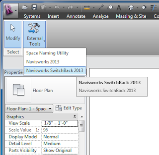
overlapping problem is gone. If you haven't tried the SwitchBack function in Navisworks, now would be a good time to try it. Note: you first have to have Revit open and Switchback turned-on:
A little more detail on the clashing: there is a new Clash Setting option called Hard(Conservative). The difference in the Hard(Conservative) and the standard Hard clashes is in how the defining triangles of an object are evaluated. The normal Hard clashes look for intersecting triangles, while the Hard(Conservative) looks for intersecting space. While this may not be the most accurate of mental pictures, think of it like this: picture clashing two pyramids. Normal Hard will only show a clash when triangle of the two pyramids intersect. Now, for Hard(Conservative) those pyramids' would be inside of a sphere (the sphere represents the pyramids' space), their three-points laying tangent on the wall of the sphere. The Hard(Conservative) then would show a clash if the spheres clash.

dennis

A little more detail on the clashing: there is a new Clash Setting option called Hard(Conservative). The difference in the Hard(Conservative) and the standard Hard clashes is in how the defining triangles of an object are evaluated. The normal Hard clashes look for intersecting triangles, while the Hard(Conservative) looks for intersecting space. While this may not be the most accurate of mental pictures, think of it like this: picture clashing two pyramids. Normal Hard will only show a clash when triangle of the two pyramids intersect. Now, for Hard(Conservative) those pyramids' would be inside of a sphere (the sphere represents the pyramids' space), their three-points laying tangent on the wall of the sphere. The Hard(Conservative) then would show a clash if the spheres clash.

dennis
May 10, 2012
BIM Coordinator
Autodesk Labs have a new product to assist with coordinating Revit with Civil 3D. This new add-in tool will allow the coordinates inside of Civil 3D be saved out as an external file, that can be imported into Revit to acquire the Shared Coordinates. This process appears to work without having to import the actual Civil file. A quicker, simpler way to make sure you Revit model has the correct coordinates.

The add-in app is written for release 2012, but I copied it to my 2013 version and it appears to work correctly.
Check it out!
The add-in app is written for release 2012, but I copied it to my 2013 version and it appears to work correctly.
Check it out!
April 26, 2012
Navisworks 2013 – My First Impressions
For an overview of the new features and enhancements for Navisworks 2013, see the link: http://usa.autodesk.com/navisworks/features/
My Favorite New Feature
Grids and Levels from Revit
In the past we had to do a lot of setup to get grids and levels to display in Navisworks, particularly difficult to acquire from Revit. 3D Grids were introduced as a Family that helped to go from Revit to Navisworks. Now in the new 2013, standard Grids and Levels will pass over to Navisworks. The only specific setup that I have found to have this feature work: The grid must be native to the project; you cannot just have the grid displayed from a link. Also, to get the Level information, you need to have at least one grid line.
In the past we had to do a lot of setup to get grids and levels to display in Navisworks, particularly difficult to acquire from Revit. 3D Grids were introduced as a Family that helped to go from Revit to Navisworks. Now in the new 2013, standard Grids and Levels will pass over to Navisworks. The only specific setup that I have found to have this feature work: The grid must be native to the project; you cannot just have the grid displayed from a link. Also, to get the Level information, you need to have at least one grid line.
 |
| Revit Grids and Levels show up now in Navisworks 2013 |
My First Bug Find
Navisworks Revit File Reader
With 2013 you can now read a RVT file just like you can read an AutoCAD DWG file. Fortunately, the folks at Autodesk did not take away the Revit Plugin so that we can export from Revit to NWC. I write ‘fortunately’ because I have discovered that the Reader doesn’t read some objects in Fine detail, while the Exporter does.
With 2013 you can now read a RVT file just like you can read an AutoCAD DWG file. Fortunately, the folks at Autodesk did not take away the Revit Plugin so that we can export from Revit to NWC. I write ‘fortunately’ because I have discovered that the Reader doesn’t read some objects in Fine detail, while the Exporter does.
I tried the main two ways the Reader looks at a RVT file: Navisworks Named View and Whole Project. My Navisworks Named View is set to Fine display.
 |
| With the Reader, Pipe and Conduit fittings are single-line. Cable Tray is Medium Detail level |
 |
| With the Exporter: Pipe, Conduit, Cable Tray and Duct all come in at Fine detail |
I have only tested RMEP objects and specifically just Duct, Pipe, Cable Tray and Conduit. Duct seems to be OK either with the Reader or the Exporter, but I wonder if this is because Duct is the same when displayed in Medium detail as with Fine detail. Cable Tray, in my test I used the Ladder type, the Reader brought it in equivalent to the Medium detail level, while the Exporter shows it as Fine. Pipe/conduit fittings do show up with the Reader, but they are shown as the coarse/medium detail level, single-line display. In contrast, the Exporter exports out the fittings as Fine detail (oddly though, the fittings come in NW a different color from the pipes themselves).
Consequently, I recommend for you RMEP folks to continue using the Exporter until a fix gets applied in an Update.dennis
March 23, 2012
Revit to PDF
First thing, if possible, use DWF. I could end the post there, but for those that find themselves having to produce PDFs, read on. For years I have used CutePDF and thought it was the best driver out there. However, the weakness in CutePDF shows up when you try to use the Print Range feature in Revit to create a batch job of multiple prints. CutePDF just fails miserably when it is fed multiple views to process. So, I took to Google looking for free PDF print drivers. I limited myself to FREE rather than trials. Why you may ask? Well, the FREE is the right price for everyone, right!?!

Drivers Evaluated: 1) BullzipPDF, 2) CutePDF, 3) PrimoPDF, 4) GIRDAC, 5) NitroPDF, 6) PDF995
My official findings:
dennis

Drivers Evaluated: 1) BullzipPDF, 2) CutePDF, 3) PrimoPDF, 4) GIRDAC, 5) NitroPDF, 6) PDF995
My official findings:
- All PDF creators are your standard Print Driver type of process.
- They each have their own printer icon in the Devices and Printer dialog.
- Each supports the Print Range batch process with the exception of CutePDF. (I did get a message from the CutePDF folks that they are working on an update that will fix this issue.)
- Most all do require the support of Ghostwriter, which will need to be installed prior to the PDF driver.
- All but one, you will need to babysit the process because they force the user to respond to their SAVE dialog box for each view selected.
- BullzipPDF is the only driver configurable to turn off the SAVE dialog. It will use the default naming conventions.
- Naming of the PDF:
- CutePDF and BullzipPDF will append the name of the PDF as: PATH_PROJECTNAME_VIEWNAME. So you will have an ugly, long name like: C_MyPDFsFolder_Project Name_View Name.pdf.
- PrimoPDF and PDF995 will append the name a bit better: PROJECTNAME_VIEWNAME. Nicer in that you don't have all PATH data included.
- GIRDAC's PDF Creator actually forces you to name each PDF processed as you go.
- NitroPDF is the nicest for naming in that it just grabs the VIEWNAME.
- Aggravations:
- GIRDAC's PDF Creator and PrimoPDF want to install other apps, so watch your prompting interface as you go through.
- PDF995 will throw-up (yeah, I meant to use that word cuz that is what it looks like on my screen) "Sponsor Commercials" with each PDF SAVE that you do. Ever hit somewhere on the web and all-of-the-sudden all these pop-ups take over your screen? Yeah, it looks like that. Complete 'show-stopper' for me.
dennis
March 20, 2012
Conduit: With or Without Fittings
Within Revit MEP, we have two different types of Families to choose from for conduit layouts. The first being "Conduit with Fittings" which will layout the conduit run showing separation lines between fittings and the straights. The second is "Conduit without Fittings" which does use fittings, but does not designate them out in the layout with the division line. In the example below you will see the greenish conduit is the "without fittings", and the cyanic conduit is "with fittings". I used two Filters to get the "look", the first filters on the conduit and conduit fittings that contains the word "without", the second filters on the conduit and fittings that do not contain the word "without". Notice how the junction boxes always fall into the "with" category.


Other than the "looks", there isn't much difference between the two families. The exception is when we get to schedules. When you right-click "Schedules/Quantities" in the Project Browser, for conduits you will find selection for Conduit, Conduit Fittings and then Conduit Run.
In my example below I chose just the "Conduit Run" and then the "Conduit". Notice that the "Conduit Run" schedule only accessed the "Conduit without Fittings". The schedule also shows the length of the continuous run that is not interrupted by a junction box. The second schedule, the "Conduit", lists out both the "with" and the "without", but only gives the actual length of the individual pieces.

dennis
March 6, 2012
Plan Region
What is it and how do I use a Plan Region? Here is a
scenario. You are working a Revit project that is a gymnasium building. There
is a basketball hoop and backboard you add to the project which is created in 3d.
Example below.

But when you look at this in plan we do not see the
basketball hoop, because the View Range is set to the default height of 4’-0”
AFF. We could change the View Range and adjust the Top Level Associate and Offset,
but this would affect the entire plan. 

After selecting the Plan Region, the items on the screen
will grey out because you are now in the sketch mode. Draw a rectangle around the
area needed to show. In this case where the basketball hoop is located. See
below


We are done! To go back and edit the View area size, area or height, just select the green dashed line and a contextual tab will appear on the Ribbon with options to edit the Boundary or the View Range. See below.


Here is where the beauty of the Plan Region comes in. Plan
Region allows us to adjust a specific area of a plans View Range. The Plan Region tool can be found under the
View tab, Create Panel, Plans View tool dropdown, and selecting Plan Region.


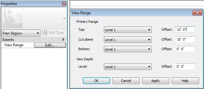
Go to Properties and select the Edit button for View Range.
Adjust the Cut plane to the height that will cut thru your object. We are
choosing 10’-0” for our Basketball hoop. The Top level and offset needs to be
above the Cut plane. See below.
Pick Ok and the Green arrow to finish the sketch. You should
now see the basketball hoop.
Pick Ok and the Green arrow to finish the sketch.
We are done! To go back and edit the View area size, area or height, just select the green dashed line and a contextual tab will appear on the Ribbon with options to edit the Boundary or the View Range. See below.

February 23, 2012
Navisworks and Revit Worksets
Sorting the objects in Navisworks based on Properties such as System Classification or System Type as assigned by Revit MEP is a common practice. The sorting is used in Clash resolution as well as Timeliner and for visualization. However, at times even the System sorting is too ‘comprehensive’ and since the model was organized by Worksets, why not use Worksets then as our Filter property? Be prepared to analyze your Workset data in Navisworks to determine what the appropriate value to filter will be. The Navisworks exporter from Revit converts the Workset data to Integer values. For an example, the default Workset1 “appears” to always come over as the integer <0> (zero). (NOTE: I wrote ‘appears’ because, so far, every test I have done it has set the Workset1 to the integer zero. But I don’t want to say it will do this each and every time, until such time that I am convinced it will.)
For my examples below, I have an NWC written from RMEP with the standard worksets: Shared Levels and Grids –and- Workset1. While in the Revit model, I created three more worksets: Mechanical, Electrical and Plumbing and modeled the systems shown with their respective Workset active. When I exported the model to Navisworks,
February 20, 2012
BIM vs. U.S. Army Corps of Engineers?
BIM, to most of us designers, has seemed to be a very slippery slope when dealing with the USACE. Many of our clients have had the same conversation with us (repeatedly) when trying to respond to an RFP. They are continually faced with the frustration of wanting to use Revit, but falling into the trap of still having to deliver the final product in "native Bentley format," as is written in many of those packages. Yet sometimes, just sometimes, we find one or two where Autodesk Products are acceptable, or even mandatory. But most of the time, the conversation always ends with, "Well, what do you think we should do? Is there anyone to appeal to?" No. . . And yes. Let me explain.
That's it. Pretty straightforward and easy to understand, if you ask me. In the end, it is up to you if you want to try to use Revit and then convert the files to Bentley, or if you even want to respond to the RFP.
The USACE is NOT against BIM; so this isn't an "us vs. them" or "them vs. BIM" situation at all. The fact is that they completely understand the need for it; but need to be very clear as to where it is important, and what flavor of BIM, or CAD, is needed in certain situations. They also have standards that must be adhered to so that FM functionality can be maintained throughout their vast portfolio of buildings. The standards are really based on two primary things: the project type and the 'client.' You see, the USACE handles two major clients for which they procure the buildings and provide FM services: The Air Force (USAF) and the Army. There are also some sub-components that modify how flexible the client may be to the format of the final delivery - regardless of what the designers or the end user (tenant) may want.
There are two major rules of thumb (and a couple of sub-rules) to follow based on the above.
- If it is an Army project, you can be 90% sure it will be done in Bentley.
- If it is one of the Centers of Standardization (COS) building types, shown in the image below, you can be almost 100% certain it will be delivered in Bentley.
- If it is not one of the COS building types there will be room for Revit or other applications. These include projects such at VA Buildings and various others.
- Regardless of whether the local base managers in California (or wherever) REALLY want Revit on a project, they still must answer to the lead district that controls the COS.
- If it is a USAF project, you can be 90% sure, or greater, that it will be done with an Autodesk product because that is what they have as their standard.
3. The RFP is final. The USACE know what they want and know where they are willing to compromise. If there is "wiggle room" for Revit, it will be in the RFP. PERIOD.
 |
| There are 41 COS products divided between 8 USACE Regions. Each Region is the controller of that particular COS and each "Tenant" must answer to the Region that controls it. |
That's it. Pretty straightforward and easy to understand, if you ask me. In the end, it is up to you if you want to try to use Revit and then convert the files to Bentley, or if you even want to respond to the RFP.
The USACE has always supplied a vast amount of work for the AEC world, and will continue to do so. Hopefully these rules of engagement will allow you to make better decisions in pursuing USACE work and, in the end, how to work better with them.
Pete Zyskowski
Pete Zyskowski
February 16, 2012
Accessing Non-accessible Parameter Data
In almost all my Revit MEP classes, when building Schedules/Tags, often the desired Parameter value is sitting there staring us in the face, but we cannot access that data, such as: Elevation -and- the secondary elevation value: Offset. In my reading of other blogs out there, I ran across this article on RevitOpEd:
dennis
who in turn references:
The Whitefeet folks (well...'fella' I should say, Mario Guttman) has provided for PUBLIC consumption some Revit utilities (I like to call these types of addins: Revit Express Tools) that you may find very useful. Particularly the Parameter Tools that will allow you to access and then assign those outta-reach parameter values to your designated parameter. It's pretty cool and mega-thanks to Whitefeet for developing and then giving them away.
This is just a heads-up post, you can learn how to download and use the utilities from the Whitefeet website.
 |
| Just the Whitefeet cat alone would win me over to Mario's utilities |
February 13, 2012
Revit to Navisworks – Slicing vs. Level Properties
In previous posts on this blog, we have reviewed two methods that can be used to slice up a Revit model by Level designation:
1) Using the built-in “3D View For Levels” and
2) Using the “DPR Slicer”.
One reason for slicing up the model is for Navisworks, particularly the Timeliner. Timeliner provides the means to build an animation of the building process. Revit does OFTEN apply Level property information to objects as they are placed. However, too often the Level designation information is assigned as <No Level> -or- there can be no level designation –or- if an object spans multiple floors, it will get associated to just the one floor from where the object ‘started’.
1) Using the built-in “3D View For Levels” and
2) Using the “DPR Slicer”.
One reason for slicing up the model is for Navisworks, particularly the Timeliner. Timeliner provides the means to build an animation of the building process. Revit does OFTEN apply Level property information to objects as they are placed. However, too often the Level designation information is assigned as <No Level> -or- there can be no level designation –or- if an object spans multiple floors, it will get associated to just the one floor from where the object ‘started’.
The following slides show a model where Filters/Search Sets were generated based on the properties Level designations.
 |
| Highlighting Level 1 showing spanning to multiple floors |
 |
| Highlighting shows those objects who are designated at Level 2 |
 |
| Highlights are Level 3 designated |
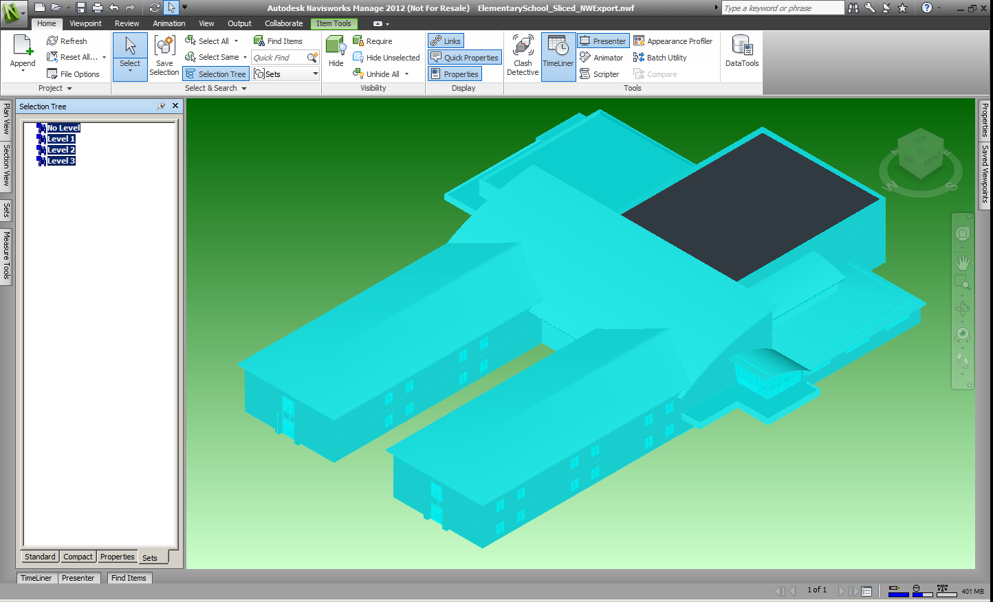 |
| Highlights of all SearchSets reveals a roof still to be assigned |
Now take a look at how the Navisworks Layers designate the objects based on the slicing from the Revit model. Each slide below shows how the model is sliced up at the physical level designation. For clarification of the view, I did setup the floor plans that generated the 3D View Section Box to put the second floor slab within the Level 2 slice by changing the View Range accordingly. Specifically, the top of the Level 1 slice is <-6.5”> below Level 2, and the Level 2 slice includes the slab by having the offset of the base at <-6.5”>.
 |
| The highlight clearly shows a line of separation of the Level 1 slice only |
 |
| Level 2 Slice |
 |
| Level 3 Slice |
Depending on the level of detail you wish to show in Timeliner, you still may have work to do, breaking up the model with Search Sets and Selection Sets. However, for a quick animation, the slicing method produces an easy generation of the Task List in Timeliner, by using the Auto-Add Tasks \ For Every Topmost Layer –or- For Every Topmost Item.

Now compare the two resulting animations:
Quick Timeliner Animation using Slicing
Quick Timeliner Animation using Filters/SearchSets
dennis

Subscribe to:
Posts (Atom)