Showing posts with label Navisworks. Show all posts

July 16, 2012

Visualizing Revit MEP Spaces in 3D

I am very visually oriented.  I like to see what I am modelling.  However, when it comes to Spaces within RMEP, you couldn't see what you are really doing. While there is a model view of Spaces within the built-in analysis interface, I still had difficulty exploring to see where I may have missed placing Spaces or where Spaces were overlapping one another. Now, working between RMEP and Navisworks, the Space model can be visualized.  Start with the settings for Revit NW Exporter and/or NW Reader:


Navisworks Option Editor for Revit File Reader  

Findings as I was exploring this feature:  You do not need to check the box “Convert room geometry” which is to convert the Spaces to construction parts.  Either way, the Spaces show up.  If using the NW Exporter from Revit, I still needed to have a 3D view as the active view when I issued the command.  If you have a Plan View up, example Level 1, then I found that my Level 1 Spaces came in flat/2D while Spaces from other floors were 3D.  You do absolutely have to Convert Entire Project.

I can see where this would help to insure all area volumes are accounted for with a Space. Look through the Space Model and find the gaps. Specifically where this helped me tremendously is in the Revit MEP Loads Analysis.  Reviewing the Spaces on the Detail tab, often you will get a warning about overlapping Space Volumes:

RMEP Loads Analysis
It can be difficult sometimes to find the overlapping.  Revit will not display the Spaces in a 3D view, which would help greatly to see and evaluate the Spaces overlapping, so using Navisworks becomes an important tool for visualization of the Spaces.
Below is a screen shot of how I setup my SearchSets and Appearance Profiler to make the Spaces easier to evaluate.

Navisworks Appearance Profiler
From here, I first tried to run a Clash Detective batch to find the overlapping Spaces, but discovered that the Spaces did not Clash with one another.  I even used the move to tool and move one Space clearly into another Space and then Clashed those two Spaces specifically, but still did not get a Result. I tried both normal Hard clash, and the new Hard(Conservative) clash (See some further notes on this below).


Then I discovered a magic setting, in the Rules tab, I clear the check mark for "Items in same group/block/cell".  Very odd, but nonetheless, I got a clash result.  Digging a little deeper, I found in Options/Model/Performance/On Load Collapse on Convert to be set to None.  Once I set this value, I was able to check the "Items in same group/block/cell" and still get clash.

Selected Spaces isolated by Hide Unselected
Now to analyze the Spaces' overlapping.  As I rotate around, I can see the problem easily:
Slight overlap
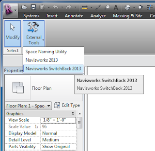
Head back into Revit MEP, put in a Space Separator, and my overlapping problem is gone.  If you haven't tried the SwitchBack function in Navisworks, now would be a good time to try it.  Note: you first have to have Revit open and Switchback turned-on:


A little more detail on the clashing: there is a new Clash Setting option called Hard(Conservative). The difference in the Hard(Conservative) and the standard Hard clashes is in how the defining triangles of an object are evaluated.  The normal Hard clashes look for intersecting triangles, while the Hard(Conservative) looks for intersecting space.  While this may not be the most accurate of mental pictures, think of it like this: picture clashing two pyramids.  Normal Hard will only show a clash when triangle of the two pyramids intersect.  Now, for Hard(Conservative) those pyramids' would be inside of a sphere (the sphere represents the pyramids' space), their three-points laying tangent on the wall of the sphere.  The Hard(Conservative) then would show a clash if the spheres clash.


dennis


April 26, 2012

Navisworks 2013 – My First Impressions

For an overview of the new features and enhancements for Navisworks 2013, see the link: http://usa.autodesk.com/navisworks/features/
My Favorite New Feature
Grids and Levels from Revit
In the past we had to do a lot of setup to get grids and levels to display in Navisworks, particularly difficult to acquire from Revit.  3D Grids were introduced as a Family that helped to go from Revit to Navisworks.  Now in the new 2013, standard Grids and Levels will pass over to Navisworks.  The only specific setup that I have found to have this feature work: The grid must be native to the project; you cannot just have the grid displayed from a link.  Also, to get the Level information, you need to have at least one grid line.

Revit Grids and Levels show up now in Navisworks 2013

My First Bug Find

Navisworks Revit File Reader
With 2013 you can now read a RVT file just like you can read an AutoCAD DWG file.  Fortunately, the folks at Autodesk did not take away the Revit Plugin so that we can export from Revit to NWC.  I write ‘fortunately’ because I have discovered that the Reader doesn’t read some objects in Fine detail, while the Exporter does.  
I tried the main two ways the Reader looks at a RVT file: Navisworks Named View and Whole Project.  My Navisworks Named View is set to Fine display.  
With the Reader, Pipe and Conduit fittings are single-line.
Cable Tray is Medium Detail level
With the Exporter: Pipe, Conduit, Cable Tray and
Duct all come in at Fine detail
I have only tested RMEP objects and specifically just Duct, Pipe, Cable Tray and Conduit.  Duct seems to be OK either with the Reader or the Exporter, but I wonder if this is because Duct is the same when displayed in Medium detail as with Fine detail.  Cable Tray, in my test I used the Ladder type, the Reader brought it in equivalent to the Medium detail level, while the Exporter shows it as Fine.  Pipe/conduit fittings do show up with the Reader, but they are shown as the coarse/medium detail level, single-line display.  In contrast, the Exporter exports out the fittings as Fine detail (oddly though, the fittings come in NW a different color from the pipes themselves).
Consequently, I recommend for you RMEP folks to continue using the Exporter until a fix gets applied in an Update.

dennis

February 23, 2012

Navisworks and Revit Worksets

Sorting the objects in Navisworks based on Properties such as System Classification or System Type as assigned by Revit MEP is a common practice.  The sorting is used in Clash resolution as well as Timeliner and for visualization.  However, at times even the System sorting is too ‘comprehensive’ and since the model was organized by Worksets, why not use Worksets then as our Filter property?  Be prepared to analyze your Workset data in Navisworks to determine what the appropriate value to filter will be.  The Navisworks exporter from Revit converts the Workset data to Integer values.  For an example, the default Workset1 “appears” to always come over as the integer <0> (zero).  (NOTE:  I wrote ‘appears’ because, so far, every test I have done it has set the Workset1 to the integer zero.  But I don’t want to say it will do this each and every time, until such time that I am convinced it will.)
For my examples below, I have an NWC written from RMEP with the standard worksets: Shared Levels and Grids –and- Workset1.  While in the Revit model, I created three more worksets: Mechanical, Electrical and Plumbing and modeled the systems shown with their respective Workset active.  When I exported the model to Navisworks,

February 13, 2012

Revit to Navisworks – Slicing vs. Level Properties

In previous posts on this blog, we have reviewed two methods that can be used to slice up a Revit model by Level designation: 
1) Using the built-in “3D View For Levels”  and 
2) Using the “DPR Slicer”.  


One reason for slicing up the model is for Navisworks, particularly the TimelinerTimeliner provides the means to build an animation of the building process.  Revit does OFTEN apply Level property information to objects as they are placed.  However, too often the Level designation information is assigned as <No Level> -or- there can be no level designation –or- if an object spans multiple floors, it will get associated to just the one floor from where the object ‘started’.
The following slides show a model where Filters/Search Sets were generated based on the properties Level designations.

Highlighting Level 1 showing spanning to multiple floors


Highlighting shows those objects who are designated at Level 2


Highlights are Level 3 designated


Highlights of all SearchSets reveals a roof still to be assigned


Now take a look at how the Navisworks Layers designate the objects based on the slicing from the Revit model.  Each slide below shows how the model is sliced up at the physical level designation.  For clarification of the view, I did setup the floor plans that generated the 3D View Section Box to put the second floor slab within the Level 2 slice by changing the View Range accordingly.  Specifically, the top of the Level 1 slice is <-6.5”> below Level 2, and the Level 2 slice includes the slab by having the offset of the base at <-6.5”>.
The highlight clearly shows a line of separation of the Level 1 slice only 


Level 2 Slice


Level 3 Slice


Depending on the level of detail you wish to show in Timeliner, you still may have work to do, breaking up the model with Search Sets and Selection Sets.  However, for a quick animation, the slicing method produces an easy generation of the Task List in Timeliner, by using the Auto-Add Tasks \ For Every Topmost Layer –or- For Every Topmost Item.


Now compare the two resulting animations:
Quick Timeliner Animation using Slicing


Quick Timeliner Animation using Filters/SearchSets

 dennis

November 17, 2011

Navisworks Batch Utility

The Batch Utility can be used to automate importing and conversion processes that are common tasks within Navisworks. There are four areas that the batch utility can assist: getting a list of design files used in a current NWF/NWD, build a new NWF/NWD with selected design files, export out NWDs for each design file listed, and accessing the Windows Scheduler to run the batches. As an example, I will select various NWCs to build a new NWF.


The Batch Utility is accessed from the Home Tab:


First, in the Input section of the dialog, I will select a specific NWC file that contains all the architectural models using the Add Files button:


November 7, 2011

Navisworks: Appearance Profiler

My favorite feature of 2012 Navisworks Manage is the Appearance Profiler. It can be used in conjunction with Search Sets to color-code your coordination models. The nice thing is that the settings can be saved out and recalled as needed in the Navisworks NWF file which makes updates to the model much easier. Pre-planning, particularly in file naming conventions, will make this feature update even with the introduction of updated models from the CAD programs. In the figure below, I built search sets based on the file names. Then I assigned those search sets to colors and level of transparency. My architectural model is green and transparent, with electrical in red, ductwork in blue and steel in yellow. Last step, SAVE the profiles listed in the Appearance Profiler to a DAT file that can be imported to any NWF when needed.

November 4, 2011

Navisworks gets stuck in Select mode

Several times this has happened to me, where Navisworks will get stuck in "selection mode" which prevents me from selecting any of the viewing functions from the Navigation bar. I recently was teaching a class, where several folks in the class had the same problem. I have tried several actions to clear the problem and have found the most reliable: right-click in the background and select SCENE. Seems to clear the problem everytime.