
December 23, 2011

Express Tools for the 21st century - it's all about the Apps

Remember the good old days when we tricked out our AutoCAD by


  • adding LSP routines embedded in toolbar buttons

  • building menus with our favorite "Express Tools"

  • customizing our digitizers (pucks) with commonly used commands

  • loading up the old "Screen Menu" with our favorite macros

Aside from merging in some popular AUGI wish list requests into future builds of AutoCAD (obsoleting many of these tools or replacing them with superior functionality), Autodesk is now providing direct access to "apps" within the AutoCAD 2012 interface.


Called "Autodesk Exchange Apps", it's an inventive and modern approach to allowing us commoners to participate in making AutoCAD (and other AutoCAD based products in the Autodesk family) more customized and productive. While many of the tools are free, others cost anywhere from 99 cents up to $500. The tools are categorized for General, AEC and Manufacturing applications, and are searchable with keywords to match specific needs. And to make the acquisition process nice and easy, once selecting an app, if it's not free, a PayPal window will appear letting you enter your PayPal or credit card information to purchase. Please note that most apps are built for use in 2012 versions of Autodesk software, so if you're not current, you can't access the "Autodesk Exchange" or run the programs listed.



Grading in the Daylight


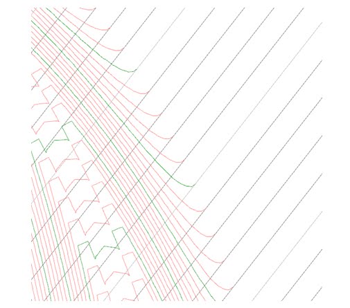
Daylight Rounding; try it, you might like it! Old school engineers and drafters still live in a world when a set of plans is a work of art and should reflect the real world. However, in the modern computing world, when finite math reaches a number, the computing stops. A great example of this is how the contours look when you are creating a corridor surface.

Contours are a major player in the older practice of hand drafting. Contours are flowing objects with few hard edges and angles in the real world. Yet when we calculate a TIN intersection, the contour will just stop and make an abrupt turn where that intersection is computed without any thought to what the end result will look like. I hear this question a lot from users: “How do I make my contours “tie in” with corridor surfaces?” By “tie-in,” they mean make the swooping arcs and look like they eventually will in real life. If you follow the link below, you’ll see an example of what old school engineers don’t want to see, how to fix it, and what the end result is.

In the image above you can see what happens when the corridor daylight subassembly calculates the intersection with the TIN and reaches true daylight: You’ll notice that the proposed contours (green and magenta) tie into the existing contours (gray) at a very harsh angle. This is typically not desirable to some engineers. Luckily, we can fake this in by setting a few parameters in the daylight subassembly. You’ll notice in the image below that I have set some rounding options in my subassembly parameters. I want a circular rounding, with a radial rounding, using a 200’ radius, and a tessellation factor of 10 (the highest factor.) And here are the results of these settings: You will notice that the contours are more “swoopy” (a term used by a not-so-old-school engineer I once worked with who actually preferred angular contours) and they tie in better. They really look more like they will in the real world once the project is built.You can play with the numbers and the options to get results that you want – the tessellation factor gives a more “rounded” look, and increasing the radius gives a more pronounced rounded tie-in. You can also experiment with the differences between parabolic and circular......
Kenneth Driscol

Pipe Systems Creation Methods

With the release of RMEP 2012, the workflow for creating Pipe Systems has taken on two different processes. The same is true for the HVAC systems as well, but we will be focusing on the Pipe Systems. The original process took us through selecting a fixture, then Create/Edit/Add to the system. The 2012 new process lets us create by duplication of the existing Pipe Systems and renaming them to the name we want. I will refer to these two methods as: 1) Create systems through selection –and- 2) Create systems through duplication. In my examples below I will be working with the Domestic Cold Water System specifically, but the process is the same for the other Pipe Systems as well.


The picture above shows the first method, Systems by Selection. The two restroom layouts are on separate Domestic Cold Water system names: DCW1 for the first floor and DCW2 for the second floor. The two system names are listed separately in the Flow Schedule and are ‘child systems’ of the Domestic Cold Water within the System Browser.

December 21, 2011

eTransmit for AutoCAD

Ok, so I saw Pete write a blog about eTransmit for Revit. As an old AutoCAD user, I felt the need to write about eTransmit for AutoCAD; the original eTransmit. And before that, Pack-n-Go.

I want to write about a feature few people use but is still very POWERFUL. You should feel and hear a deep dark voice as you read the word POWERFUL.

You can use eTransmit to not only automatically compress all your AutoCAD drawings into a .zip file or a self executible .exe file, BUT AT THE SAME TIME you can use e-Transmit to AUTOMATICALLY save your AutoCAD drawings to an older DWG version within the .zip or .exe file. Your orginal DWG files on your computer or on your server are not saved back to an older version, only the copies made part of the zip file are converted. So when do you think that will be a feature in Revit's eTransmit?
Mark Petrucci

December 19, 2011

eTransmit for Revit

While we haven't experimented with this yet, this may be worth checking out.  Autodesk Labs has released an update for Revit eTransmit.  Everyone gets nasty messages from a workshared Revit model when you are the one that is getting a file from a consultant. Hopefully, this makes sending (and receiving) the Revit file a bit easier - and makes sure that everyone is getting the right info.

From Autodesk:
With eTransmit for Revit, you can:
  • Copy and detach a Revit model and associated files to a single folder for internet transmission. This removes the typical error messages when you copy central files using the operating system.
  • Locate dependent files automatically and include them in the transmittal folder, helping to reduce the possibility of error. All dependent files are automatically converted to use relative paths so the dependent files can be located by the model.
  • Choose to include related dependent files such as linked Revit models, CAD files, DWF™ markups, decal images, and external keynote files. You can transmit any Revit (.rvt) model that has beenupgraded to be compatible with a 2012 Revit software product.
  • Transmit models that are using file-based worksharing or server-based worksharing. eTransmit for Revit will also work with non-workshared Revit models.
View of the eTransmit dialog.


-Pete Zyskowski

Explore Multiple Design Alternatives

AutoCAD Civil 3D enables you to explore multiple options, ultimately helping you produce an optimized design. The integration of imagery and geospatial data assists in identifying an optimal solution early in the overall process, helping to save time and money.

• Import geospatial data, such as soil types, land use information, and environmental constraints to more quickly analyze and better understand the probable impacts of different alternatives.

• Use imagery and terrain models from Google Earth™ mapping services and other sources to help visualize the ecosystem of a project.

• Most project data—such as survey information, surfaces, profiles, horizontal alignments, and
corridor models, as well as related annotations and labels—have predictable relationships with other elements in your design. This results in the dynamic updating of model elements when related elements are changed.

• AutoCAD Civil 3D includes terrain shaping tools that support large-surface models while
maintaining dynamic relationships to source data, including contours, break lines, corridor models, and grading objects.

• Use surfaces as references for creating profiles, sections, and corridors. Any changes to the source data result in automatic updates to surfaces and references, which helps you save time and reduce errors. This means that several alternatives can be evaluated quickly since immediate feedback is given, helping to ensure important design constraints are held, such as project limits staying within existing rights of
way.

Built-In Standards


Standards are the universal language of civil engineering. Almost all projects need to respect local constraints for steep slopes, pipe layout, minimum parcel size and road frontage, sight distances, road curvature, and more. Additionally, construction documents need to use the appropriate line types, line weights, and symbology to be readable for construction and accepted by regulating agencies. Designers can make changes with more confidence because AutoCAD Civil 3D 2012 software helps them to meet the design criteria mandated
by the customer and various third parties.


  • AutoCAD Civil 3D 2012 software has built-in tools that help reference and report violations of industry requirements, like AASHTO and TAC standards.
  • Corridor models can be built using assemblies with parametric constraints based on agency requirements.
  • Customize tables to help you adhere to unique standards that are enforced by local agencies.
  •  Maximize parcel yield and green space using built-in tools to help meet local standards for size, frontage, and setback. Use interactive editing tools to preview changes and refine layouts without your established constraints before deciding on a final design.
  • Autodesk Storm and Sanitary Analysis, included with Civil 3D, is based on industry-leading hydrologic models such as EPA SWMM Version 5, TR-20, TR-55, and other regional models, which facilitates submittal of stormwater management reports in many jurisdictions.