November 10, 2011

AutoCAD

I've been using AutoCAD since Release 11, when it was DOS based. A lot has changed since then, and for the better! I enjoy finding new tips, tricks and little things to help make life easier.


Here is something simple but worth it. Osnap - Parallel. This Osnap allows you to draw a new line or object parallel to a reference object. You start the line command, and then using the Parallel Osnap hover over the reference line. You will see a symbol looking like this "//" over the line. It will disapear as you move off, but once you are lined up parallel with the reference line and your new line, the symbol will reappear and you can draw your line parallel. Simple but effective! Enjoy!

November 9, 2011

3ds Max Design - Backburner

Backburner is a batch network rendering utility that comes with 3ds Max and Maya. This is used when you want to render multiple images to several computers/nodes.

It has 3 main pieces. Manager, Monitor and Server. The Manager and Monitor are usually installed on the same computer. This is typically your computer that is running 3ds Max, but does not have to be. Some companies have a dedicated Graphics computer that would work well to have this installed on. Also the Server piece needs to be installed on all the computer nodes. The name Server is a bit misleading, because it in fact gets installed on the workstation. A true network server doesn't really have a part in all of this. Also, 3ds Max needs to be installed on the computers with the Server piece. 3ds Max is needed to process the information. It does not need to be registered or licensed. You can install up to 9,999 installations of 3ds Max for the Rendering farm.

So the concept is that you have a 3ds Max model and want to render several shots or an animation. Go through your regular process in Max that you would normally do to render, but at the end use the Batch Rendering to load your renderings and animations. Then select the checkbox "Net render" button in the lower left and then the "render" button to send the images to be processed. The Manager and Monitor will take over from there. They will pass on the images to the Server nodes for processing

QTO and Revit Underlays

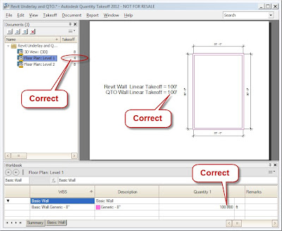
Do you use QTO with Revit Models? You should be aware of a bug with QTO and Revit Views that use another Revit View as an Underlay. QTO will quantify any object in the current view including objects in the underlay. A very easy test is to create four walls on Level 1 that form a rectangle, 20'x30'. Create 4 walls on Level 2 that form a rectangle, 20'x15'. Place the Level 2 walls directly above the Level 1 walls and keep Level 1 as in underlay to Level 2. Export your Revit model to DWF and import into QTO. Do a model takeoff and look at the linear takeoff for each level.


You will see QTO has counted for Level 1: 4 Walls . Total linear takeoff - 100'.


You will see QTO has counted for
Level 2: 8 walls (4 on Level 1 and 4 on Level 2). Total linear takeoff of 170' instead of the correct 70.


The good news is the Total Linear Takeoff for the PROJECT is correct. It is NOT Level 1: 100' + Level 2: 170'. It calculates the project total for Level 1:100' + Level 2:70'=170'.

Mark Petrucci

November 8, 2011

Setting Up 3D Views For Levels

When starting a new project in Revit, I typically create 3D views for each level in the project.  To do this I use the View Cube to assist me in creating the views.  I typically do not care for the View Cube for orbiting or adjusting my views.  I usually use my wheel on my mouse with the shift key to orbit, but I have found the View Cube to be very helpful for this particular task.

To set up a 3D view for each level, you could manually achieve this by turning on the Section Box in the Properties of the view and use the grips to drag the Section Box to display just the desired level.  This is very cumbersome and sometimes hard to get the grips to be where you want them to be.

An easier, quicker way to create a 3D view for each level is to use the Orient to View option in the View Cube right click menu.  This can be done by opening a 3D view and hovering over the House icon on the View Cube, and right clicking to open the right-click menu.


In the right-click menu, select Orient to a View, Floor Plans, and then select the desired floor plan to orient to.

The view will automatically crop the view using the Section Box to match the View Range for the view that was selected.  It will also rotate the view to view it from the Top direction.  You can orbit the view any direction you want but the view is now cropped to match the floor plan's View Range.


I typically create a 3D view for each level in my project.  These are very useful, especially once the building is totally closed in and it is hard to see inside of it.


Plant 3D size editing is a breeze


In AutoCAD Plant 3D 2012, you can change the size of a valve just by going to its properties and making a simple change.


Select the valve, RMC on the valve and select Properties to see the size value.

In Properties, change the size by selecting the drop-down list and choose the new size.

Once the size is changed, close Properties and see the result. There is no need to add reducers to your pipeline. Reducers are automatically added to both sides of the 4" weldneck flanges.

Happy Routing!

Revit - Surface pattern

A question came up recently about how to remove the surface pattern from a slab when viewing it from a plan view.


First off, find out what the material is on the slab that is being displayed. Select the slab, go to "Edit Type" in the Properties. Under Structure row, pick the Edit button. Find the top material. Lets say concrete for our example. Pick on it and select the "..." button. This will open up the Materials. The selected material should be pre-highlighted. Select it and go to the Surface Pattern area on the right. Change the material to "none". Select OK three times and you will be back to your view, which is now updated to not show the surface material.

Note: This will remove the surface pattern for all of the slabs with that same material. There are some other options to duplicate the slab type and material, if you want slab "A" to show surface material, and slab "B" not to show the surface material.

Editor's Note: You can also select and right click on the slab and graphically override the category or object in that particular view if you don't want the material to change globally.

The 12d Data Extension for AutoCAD® Civil 3D® 2012

Move forward with no worries, DOT......

The 12d Data Extension for Civil 3D 2012 enables data from 12d® Model™ software by 12d Solutions Pty Ltd to be imported and used within AutoCAD Civil 3D 2012 software.
The extension provides support for 12d Model ASCII files from all known
versions of 12d Model software up to and including Version 9.0.


Supported 12d Model data types include:

Alignments andprofiles
Super strings
Drainage strings
TIN’s
Text strings