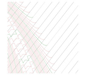


Daylight Rounding; try it, you might like it! Old school engineers and drafters still live in a world when a set of plans is a work of art and should reflect the real world. However, in the modern computing world, when finite math reaches a number, the computing stops. A great example of this is how the contours look when you are creating a corridor surface.
Contours are a major player in the older practice of hand drafting. Contours are flowing objects with few hard edges and angles in the real world. Yet when we calculate a TIN intersection, the contour will just stop and make an abrupt turn where that intersection is computed without any thought to what the end result will look like. I hear this question a lot from users: “How do I make my contours “tie in” with corridor surfaces?” By “tie-in,” they mean make the swooping arcs and look like they eventually will in real life. If you follow the link below, you’ll see an example of what old school engineers don’t want to see, how to fix it, and what the end result is.
In the image above you can see what happens when the corridor daylight subassembly calculates the intersection with the TIN and reaches true daylight: You’ll notice that the proposed contours (green and magenta) tie into the existing contours (gray) at a very harsh angle. This is typically not desirable to some engineers. Luckily, we can fake this in by setting a few parameters in the daylight subassembly. You’ll notice in the image below that I have set some rounding options in my subassembly parameters. I want a circular rounding, with a radial rounding, using a 200’ radius, and a tessellation factor of 10 (the highest factor.) And here are the results of these settings: You will notice that the contours are more “swoopy” (a term used by a not-so-old-school engineer I once worked with who actually preferred angular contours) and they tie in better. They really look more like they will in the real world once the project is built.You can play with the numbers and the options to get results that you want – the tessellation factor gives a more “rounded” look, and increasing the radius gives a more pronounced rounded tie-in. You can also experiment with the differences between parabolic and circular......
Kenneth Driscol

No comments:
Post a Comment
Note: Only a member of this blog may post a comment.