Pages

November 30, 2011

Cloud - Documents


In a continuation from a previous blog post on the Cloud... There is also something in the Autodesk Cloud called “Documents”.


This, as the name might simply imply, is a place in the cloud to store files, documents, images, etc. and be able to manage and share them with team members, colleagues and clients. Folders and categories can be created; files can be edited via AutoCAD WS, along with mobile app. to view on iPad or iPhone devices.
Within Documents the files can be shared to other users with rights assigned to the files controlling the access. Also recent activity can be tracked along with comments that can be left by users about the files. There are even Versions of the file that can be tracked. See image below for document details.
One other comment to add is that Autodesk was offering potential, non-subscription, users to signup and get 1 gig for free!

To the Cloud!


Is your head in the clouds trying to understand the “cloud” and Autodesk Cloud in particular?

Lets see if we can give some explanation. Autodesk Cloud is a technology that is gaining interest with users with the ability to perform tasks without installing applications to local resources. We can use the cloud for several purposes... We can upload, share and edit drawings in the cloud using AutoCAD WS. We can view files with Design Review mobile app for iPhone and iPad devices. Rendering files in the cloud, along with the ability to upload and share documents.

Let's take a closer look at cloud services for rendering and documents.

Autodesk Cloud Rendering
Currently Revit can render models to the cloud via the Subscription download. An Autodesk login account needs to be created.  The concept behind Cloud rendering is simple… render your model in the cloud (the internet) without tying up your computer for an extended amount of time. Also, if you are running a marginal computer that barely meets the minimum requirements, this option of rendering in the cloud could save you a big investment in hardware and equipment.

I must add, that you can use AutoCAD as well for cloud rendering. Currently these are the only two products Autodesk has that can offer the cloud for rendering.

So, how does this all work…

After downloading the Cloud rendering subscription piece, you will have access to in under the “Add-in” tab. This will give you access to either start the cloud rendering process or access your online gallery.
You’ll need to login or create an Autodesk account to access you rendering and galleries. A simple few setup items to create account and you can sign-in.


Select a source file to upload for either Revit or AutoCAD.


Change rendering settings
Here we have a preset listing of settings to change to adjust the results of the rendering. From testing, I have found varied results from local rendering vs. cloud renderings. This is due to different processes that cloud rendering uses instead of traditional CPU processing power.

Rendering run… could take a couple minutes.

A report is emailed upon completion of rendering

Note: Each user is provided 3 gigs of storage per user. This may become a paid service in next release.

November 29, 2011

Revit Server Between Different Companies? It's Do-able!

Revit Server.  Let's review quickly what it was meant to do and the problems that it solves.  Then we'll take it to the next level.

Revit Server was designed to help a SINGLE company with distributed, satellite offices work on a single model.  In that scenario, everyone is on the same wide area network with no worries about security or other IT issues to get the server up and running.  In the traditional model to the left, we are using some sort of VPN for synchronization, or an FTP site to share a model that has been sliced into pieces so that each office can work on their piece of the project.  This can work, but only if the pieces of the puzzle are cleanly delineated, which is very rare on a project of the size and magnitude that would require

November 22, 2011

AutoCAD Quick Send to 3ds Max Design


Autodesk Labs announced today a labs product tool for sending AutoCAD files to 3dS Max Design with a quick transfer. This is a Plug-in that shortens the process of sending AutoCAD data traditionally to 3ds Max Design. This preview in Labs will be available up to March 1, 2012. In several cases these Labs technologies end up in the new release.

You need to download the "AutoCAD Quick Send to 3ds Max Design" from the Autodesk Labs Preview site. But first you must have the latest Service Packs install in AutoCAD and 3ds Max Design or it will not work.

The image example at the top is the "Workflow" panel for sending the data to 3dS Max. Within the panel are options to "run" or "edit" the settings on how data is transferred. The actual "Quick Send..." button is a dropdown for additional workflows you can create. These workflows can be shared to other users.

A nice feature is that the workflow can run in the background and you can continue being productive working in AutoCAD. A helpful notification will pop-up informing you on the transfer progress and completion.
This Preview is only available for AutoCAD and not AutoCAD Architecture.

Revit MEP - Non-selectable Duct/Pipe

Have you ever wanted to setup a view showing duct and pipe, but didn't want to be able to select the duct or pipe? Here is a way:


1) Add some insulation to the duct/pipe, including the fittings.


2) In VG, turn off the duct/pipe and fittings, leave on the insulation.


3) Done. Now you can see the insulation, but cannot select.

November 21, 2011

Revit - What's your favorite color?

I thought about this a few years ago teaching Revit Architecture to a group of young high school students. Yes, high school students are learning Revit. Most new users of Revit forget to select the object they want to modify. While it's not required, selecting the element(s) first displays a contextual tab that shows tools available to the designer. In addition, they forget they can double-click on the blue datum target to quickly jump to associated floor plan views.

To help students, I tell them their new favorite color when using Revit is blue. Whenever you want to modify an element, click on it and make it blue. If you need to change a dimension, select the object you want to modify so the dimension text turns blue and now you can change the dimension text value.

Blue is also the typical color of hyperlinks on webpages so clicking on a blue call out tag will take you to the matching view. If you want to jump to view, you can double-click on a visible datum, call out tag, building section, wall section and/or detail head.

However, when you hover over an element, its pre-selected color is also blue so students might think they don't have to click their mouse. So what if you can change the color of elements depending if they are pre-selected or selected? Well you can.
Click 4Options4Graphics tab. (Click image below to enlarge)

In the example above, simply hovering over a wall will make it green but once selected it turns red. Of course, if blue is your favorite color...
Mark Petrucci

November 17, 2011

Revit Levels – Live vs. Dead


When using Revit Levels, we can create levels with floor plan views, or we can create levels that do not have floor plans associated with them. These are usually used when you want to constrain or lock elements to the “dead” level, but do not need the floor plan. This could be a T.O. Steel level, or some other level for coordination. Live levels are shown with blue datum, while dead levels are shown as black datums.
Don't delete those dead levels! Here are two reasons. First, if the dead level has objects constrained to them, there is a good chance that item will be deleted along with the level. Secondly, dead levels can be converted to a live level with a floor plan associated with them. "How," you ask?... That will have to wait until I see you in class.

To Borrow or not to Borrow, that is the question!


I had a meeting with a client a while back about Revit setup and configuration. One of the topics that came up was Worksets. What are the best practices for Worksets? Worksets are interesting to understand when you first start learning about them (that's a separate blog at a later date), but instead of the traditional "Checking Out" feature, I have had a lot of success with just borrowing. This entails not checking out a Workset, but allowing team members to borrow items when needed. This system doesn’t work for every office or studio, and all team members need to be on board with the idea. It's much more flexible to select an item and click on the "little boxes" icon and make them editable, than to go thru the process of checking out a set, which restricts team members form accessing items in the project. Once you sync to Central you relinquish the element and move on. Again, this doesn’t work for everyone, but it can be very effective and help to run a project faster. Give borrowing a chance!

Navisworks Batch Utility

The Batch Utility can be used to automate importing and conversion processes that are common tasks within Navisworks. There are four areas that the batch utility can assist: getting a list of design files used in a current NWF/NWD, build a new NWF/NWD with selected design files, export out NWDs for each design file listed, and accessing the Windows Scheduler to run the batches. As an example, I will select various NWCs to build a new NWF.


The Batch Utility is accessed from the Home Tab:


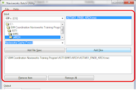
First, in the Input section of the dialog, I will select a specific NWC file that contains all the architectural models using the Add Files button:


AutoCAD - Scaling

No it's not a Mitsubishi car symbol. Its an icon of the cross section of a an architectural scale. The actual tool is for Annotative scaling of annotation objects like text, dimensions and graphical symbols. This feature was added a few releases ago, but I realized from teaching, that there are a lot of folks who are still working in Model Space, doing things the old way, and aren't aware of Annotative scaling.

By using the annotative scaling, it takes care of all the busy work of text sizes when changing scale. The quick, down and dirty of making it work, is to have all of these buttons turned on. They will light up and will show the light bulb and lightening bolt in yellow once on. Also you need to be using Annotative text or dimensions. Set your scale and start drawing. The text and dims will display at the correct height per your settings and when you change the scale they will update. The last cool thing is that the text will scale according to the Viewport scale. Annotative scale rocks! Enjoy!!

November 15, 2011

T.O.S. vs. F.F.E. – What’s your pleasure?


Top of Steel (T.O.S.) or Finished Floor Elevations (F.F.E.) Why do you ask? A recent debate has been going on with architects and engineers on what is the typical datum level to reference from.

There are pros and cons potentially to setting up levels at FFE vs TOS. The first would be coordination and the chance for human errors. Also depending if you are an in the architectural discipline as an Architect vs. the structural industry as a Structural Engineer.

What is the industry standard?
An architect would say FFE. This however does not include carpeting, tile, etc. This is the floor to floor heights.

An engineer would say TOS. This is what is usually built first and erected in the field. Even if the steel is sloping, the TOS reference datum plane is still established.

So how can we, from a technology, computer BIM application benefit, or should I say coordinate this industry dividing quandary? Constraints are a wonderful option when looking at Revit (Architecture, Structure, and MEP) for a solution.

Using Existing data
What if we are using the other discipline's file and linking them in the model, and the levels are already established? Linking and Copy Monitor tool. Copy monitor allows users of different disciplines to do just what the name implies “copy” the existing levels, and then allowing the user to move/offset the level to their specific location, for their needs. The levels can then be constrained so if there is movement from either disciplines, a notification will be presented.
Which ever method you choose, Revit has the tools built-in to help you accomplish you needs and coordinate other level references, allowing you to focus on your project.

BIM floor level datum lines should be:

Revit Home Tab Tools Are Greyed Out!

This happens ALL the time with new students. At some point during my class, a student will comment about the Home tab and most of the tools on the Home tab as being unavailable or greyed out. This literally happens with every new class.


Revit does this on purpose. The reason this happens is because you are in the middle of another command which places you in edit mode or what we use to call sketch mode. I tell students to look at the upper right corner of their ribbon and if they see a colored tab, they need to select that tab and make it active. Once a student realizes this, they have to either finish edit mode by selecting the green check or cancel edit mode by selecting the red X.
Mark Petrucci

Revit Guide Grids. What?

Guide Grid: a little know tool in Revit to help you align views so that they appear in the same location from sheet to sheet. For example, if you place each multistory floor plan view on their own sheet, Guide Grids can help you locate each floor plan view so they appear in the same location sheet to sheet.

Here's how to use Guide Grids:


  1. Open a sheet view


  2. Go to the View tab 4 Sheet composition Panel 4 Guide Grid tool


  3. Name the Guide Grid something logical. "E1 Sheet Size" for example.You can use the same Guide Grid on other sheets by simply looking at the sheet properties. Listed at the very bottom of the property panel is a parameter named Guide Grid. Change this from NONE to the name of your new Guide Grid.
Now for the two VERY IMPORTANT tricky parts.

When you apply the same Guide Grid to multiple sheets, ANY changes to the Guide Grid are applied to ALL sheets. If you move the Guide Grid on one sheet or change the extents, it will move or change on every other sheet that uses the same Guide Grid.

You can't move and snap your title sheet to the OUTSIDE edge of the Guide Grid. However, you can move and snap your sheet to one of the interior grid lines. My recommendation, is to move the Guide Grid ONE TIME! Don't move it on every sheet. If the Guide Grid is not correct on one sheet but it is on others, then move the title block and not the Guide Grid on the one incorrect sheet.

Once you see a Guide Grid on your sheet, you can add views to the sheet. Then move your view so in aligns at a Guide Grid intersection. However, you can only move or align column grids, levels, and reference plans to the guide grid. You can't align walls to the guide grids. If you want to align a specific location you can always add a reference plane to that location and then move and snap the view from the reference plane to an INTERIOR Guide Grid intersection.

Here's a tip. I like to lighten the Guide Grid. Go to Manage Tab4Settings Panel4Object Styles 4Annotation Objects Tab. You can lighten the color of the Guide Grid lines here.

And finally... If you keep the Guide Grid on in sheet views, also pin it so you don't accidentally move it. Make sheets with Guide Grid on as part of your template file. People will wonder where there came from and how to use them.
Mark Petrucci

November 14, 2011

Embedded Schedules in Revit MEP

Not too many users are aware that in Revit MEP schedules can be embedded into other schedules.  This feature is only available in Revit MEP and not in Revit Architecture.  And, it is only available in certain types of Revit MEP schedules.  Embedded schedules can be inside of Room and Space schedules and System schedules (Pipe Systems, Duct Systems and Electrical Circuits).

This feature will allow you to create a schedule inside of another schedule.  This could be used if you want to list what fixtures are in a space, or what pipes are in a system, or what devices are on a circuit.

To create an Embedded Schedule, you begin by creating a Room or Space or System schedule as you typically would.  You can add the fields desired, configure the sorting method, modify the formatting.  In the Schedule Properties dialog, there is a new tab at the end for Embedded Schedule.


Here you can select what type of schedule you would like to be embedded and then you can select Embedded Schedule Properties, to modify the properties of the embedded schedule.  You go through the same steps to create the embedded schedule as you would when you create a normal schedule.  You can add the fields desired, configure the sorting method, and modify the formatting.


Space Schedule with Embedded Light Fixture Schedule
This is a great way to show what is in a space, what is in a system, or what is on a circuit.  I am not sure why this is limited to Revit MEP. I am sure that architects could use this if it were available.  This might make my wish list for future releases.

The Best and Worst Thing About AutoCAD

First, I remember my English teacher telling me not to use the word "thing". Oh well (or is that oh good?)

I tell my students this all the time. "The best thing about AutoCAD is you can create as many layers as you want. Can you guess the worst thing about AutoCAD? The worst thing about AutoCAD is that you can create as many layers as you want."

Layers are a great way to organize your drawing. However, there are some well known best practices when it comes to layers. First, use only as many layers as you need. Do not create a bunch of layer just because you can. Too many layers just means more layers to turn on and off, freeze or thaw. Do you need a separate layer for desks and chairs or can you put them on one layer called furniture? Maybe you do and maybe you don't. If you haven't thought about it before, maybe this will get you thinking. I know one firm that puts stairs and elevators on the same layer; it works for them.

Second, I recommend using a layer naming convention. I would really like to DEMAND that you use a layer naming convention but America is free country, so I'll let you choose. Here is what I tell my students: As you read the layer name from left to right, the layer name should be more general on the left and gets more specific as you move to the right.

I can name a layer NEW WALLS but a better way to name the layer is A-WALLS-NEW. I start "A" for architecture, "WALLS" for well.... walls. "NEW" describes a more specific wall, a new wall. I could then do a DEMO wall and a LOW wall. Don't forget about the first rule above though, only make as many layers as you need. Another reason for following this layer naming convention is to help alphabetically group layers together.Which layer list to the right is more organized?

Notice how all my architectural layers are grouped together and how all my furniture layers are grouped together.

The best thing about AutoCAD can be better if you follow these two simple rules.
Mark Petrucci

November 11, 2011

Revit Slab Edge - Quick Tutorial

This is a quick How-To that was published a while back on my You-Tube channel, but may still be of some use to everyone.  It goes over creating profiles and then using them to create new slab edge types.


For HD, you can still get the original here: http://www.youtube.com/watch?v=zIAd7jTaAFY

AutoCAD - < > Greater Than / Less Than

No its not gang symbols. Its the greater than / less than symbols - hand gesture. I show my students this when teaching AutoCAD to get them into the thinking of using and thinking of these symbols because in AutoCAD in the command line they represent the default value or last value used. Which means you can save time by not having to do additional typing versus just hitting the enter key to accept whats in the "<>" value. So we can save additional time by using the default or previous used value by reading the command line with the greater than and less than symbols "<>". Remember the graphic and save your self some time!

AutoCAD Tablet - I regress


I found the fold up insert that came in the AutoCAD Release 14 box for tablet overlay. This is a real blast from the past. The overlay sat over top of the Digitizer tablet. The buttons could be programmed to make drawing faster. Too bad AutoCAD and the computers at the time were so slow.

Life is easier using Autodesk 2012 products. First of all, there are no Tablets. Now if I can find my old 24+ button puck around here somewhere?

November 10, 2011

AutoCAD

I've been using AutoCAD since Release 11, when it was DOS based. A lot has changed since then, and for the better! I enjoy finding new tips, tricks and little things to help make life easier.


Here is something simple but worth it. Osnap - Parallel. This Osnap allows you to draw a new line or object parallel to a reference object. You start the line command, and then using the Parallel Osnap hover over the reference line. You will see a symbol looking like this "//" over the line. It will disapear as you move off, but once you are lined up parallel with the reference line and your new line, the symbol will reappear and you can draw your line parallel. Simple but effective! Enjoy!

November 9, 2011

3ds Max Design - Backburner

Backburner is a batch network rendering utility that comes with 3ds Max and Maya. This is used when you want to render multiple images to several computers/nodes.

It has 3 main pieces. Manager, Monitor and Server. The Manager and Monitor are usually installed on the same computer. This is typically your computer that is running 3ds Max, but does not have to be. Some companies have a dedicated Graphics computer that would work well to have this installed on. Also the Server piece needs to be installed on all the computer nodes. The name Server is a bit misleading, because it in fact gets installed on the workstation. A true network server doesn't really have a part in all of this. Also, 3ds Max needs to be installed on the computers with the Server piece. 3ds Max is needed to process the information. It does not need to be registered or licensed. You can install up to 9,999 installations of 3ds Max for the Rendering farm.

So the concept is that you have a 3ds Max model and want to render several shots or an animation. Go through your regular process in Max that you would normally do to render, but at the end use the Batch Rendering to load your renderings and animations. Then select the checkbox "Net render" button in the lower left and then the "render" button to send the images to be processed. The Manager and Monitor will take over from there. They will pass on the images to the Server nodes for processing

QTO and Revit Underlays

Do you use QTO with Revit Models? You should be aware of a bug with QTO and Revit Views that use another Revit View as an Underlay. QTO will quantify any object in the current view including objects in the underlay. A very easy test is to create four walls on Level 1 that form a rectangle, 20'x30'. Create 4 walls on Level 2 that form a rectangle, 20'x15'. Place the Level 2 walls directly above the Level 1 walls and keep Level 1 as in underlay to Level 2. Export your Revit model to DWF and import into QTO. Do a model takeoff and look at the linear takeoff for each level.


You will see QTO has counted for Level 1: 4 Walls . Total linear takeoff - 100'.


You will see QTO has counted for
Level 2: 8 walls (4 on Level 1 and 4 on Level 2). Total linear takeoff of 170' instead of the correct 70.


The good news is the Total Linear Takeoff for the PROJECT is correct. It is NOT Level 1: 100' + Level 2: 170'. It calculates the project total for Level 1:100' + Level 2:70'=170'.

Mark Petrucci

November 8, 2011

Setting Up 3D Views For Levels

When starting a new project in Revit, I typically create 3D views for each level in the project.  To do this I use the View Cube to assist me in creating the views.  I typically do not care for the View Cube for orbiting or adjusting my views.  I usually use my wheel on my mouse with the shift key to orbit, but I have found the View Cube to be very helpful for this particular task.

To set up a 3D view for each level, you could manually achieve this by turning on the Section Box in the Properties of the view and use the grips to drag the Section Box to display just the desired level.  This is very cumbersome and sometimes hard to get the grips to be where you want them to be.

An easier, quicker way to create a 3D view for each level is to use the Orient to View option in the View Cube right click menu.  This can be done by opening a 3D view and hovering over the House icon on the View Cube, and right clicking to open the right-click menu.


In the right-click menu, select Orient to a View, Floor Plans, and then select the desired floor plan to orient to.

The view will automatically crop the view using the Section Box to match the View Range for the view that was selected.  It will also rotate the view to view it from the Top direction.  You can orbit the view any direction you want but the view is now cropped to match the floor plan's View Range.


I typically create a 3D view for each level in my project.  These are very useful, especially once the building is totally closed in and it is hard to see inside of it.


Plant 3D size editing is a breeze


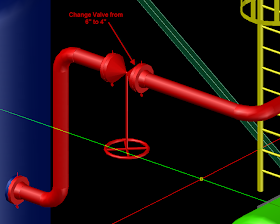
In AutoCAD Plant 3D 2012, you can change the size of a valve just by going to its properties and making a simple change.


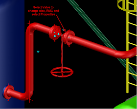
Select the valve, RMC on the valve and select Properties to see the size value.

In Properties, change the size by selecting the drop-down list and choose the new size.

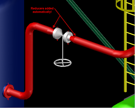
Once the size is changed, close Properties and see the result. There is no need to add reducers to your pipeline. Reducers are automatically added to both sides of the 4" weldneck flanges.

Happy Routing!

Revit - Surface pattern

A question came up recently about how to remove the surface pattern from a slab when viewing it from a plan view.


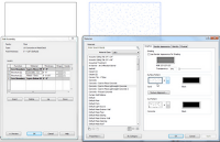
First off, find out what the material is on the slab that is being displayed. Select the slab, go to "Edit Type" in the Properties. Under Structure row, pick the Edit button. Find the top material. Lets say concrete for our example. Pick on it and select the "..." button. This will open up the Materials. The selected material should be pre-highlighted. Select it and go to the Surface Pattern area on the right. Change the material to "none". Select OK three times and you will be back to your view, which is now updated to not show the surface material.

Note: This will remove the surface pattern for all of the slabs with that same material. There are some other options to duplicate the slab type and material, if you want slab "A" to show surface material, and slab "B" not to show the surface material.

Editor's Note: You can also select and right click on the slab and graphically override the category or object in that particular view if you don't want the material to change globally.

The 12d Data Extension for AutoCAD® Civil 3D® 2012

Move forward with no worries, DOT......

The 12d Data Extension for Civil 3D 2012 enables data from 12d® Model™ software by 12d Solutions Pty Ltd to be imported and used within AutoCAD Civil 3D 2012 software.
The extension provides support for 12d Model ASCII files from all known
versions of 12d Model software up to and including Version 9.0.


Supported 12d Model data types include:

Alignments andprofiles
Super strings
Drainage strings
TIN’s
Text strings

November 7, 2011

3ds Max Design - Project Folders

Project folders in 3ds Max Design are a great helpful tool! By setting the project folder, this allows 3ds Max to search, or look, in the folder of that project directory. This works well for when other people are working on a project with you, or if you have to come back to a project after a few weeks. Setting the project to be active then re-paths the search folders in 3ds Max to look for presets, scenes, import/export and other project specific folders.

Found under the Application big "M", and then Manage, setting the folder is easy, either to an existing folder, or creating a new one.

Navisworks: Appearance Profiler

My favorite feature of 2012 Navisworks Manage is the Appearance Profiler. It can be used in conjunction with Search Sets to color-code your coordination models. The nice thing is that the settings can be saved out and recalled as needed in the Navisworks NWF file which makes updates to the model much easier. Pre-planning, particularly in file naming conventions, will make this feature update even with the introduction of updated models from the CAD programs. In the figure below, I built search sets based on the file names. Then I assigned those search sets to colors and level of transparency. My architectural model is green and transparent, with electrical in red, ductwork in blue and steel in yellow. Last step, SAVE the profiles listed in the Appearance Profiler to a DAT file that can be imported to any NWF when needed.

The Volumes Dashboard Extension for AutoCAD® Civil 3D® 2012


Playing in the Dirt.........

The Volumes Dashboard Extension for AutoCAD Civil 3D 2012 software provides a streamlined interface for design and construction professionals to calculate, report and visualize surface volumes within AutoCAD Civil 3D 2012 software.
Refining earthworks through iterative design is a common operation that is
performed throughout the design and construction process on infrastructure
projects. This extension can streamline and help optimize the current process
in AutoCAD Civil 3D 2012; it will also provide an easy to follow workflow for
common tasks, helping new Civil 3D users become productive, more quickly.

3ds Max Design - tips


Here
are a couple of quick tips from a recent 3ds Max Design class
that I was teaching...

3d model rotate - hold down the Ctrl key and mouse wheel to spin the model.

Cloning - Move tool, hold down Shift. This will duplicate the object, but giving you the option of Copy, Instance or Reference. Instance vs. Reference... Instance you can change any of the object copied and it updates all of them. Reference, you need to change the original, to update the others.

Save Copy - This saves your scene and adds a number sequence to the end of the file name.

Mirrored Door Number Bug

Door schedules in Revit are great. However, if you include room numbers with your doors, you should know about a bug. Door schedules can include data from a "To Room: Number" parameter and "From Room:Number" parameter. The image below shows a simple floor plan with 5 room objects and 4 doors. Looking at a floor plan view, all the doors swing From Corridor Room Number 100 and swing into their own unique room. However, you will notice on the door schedule that Door Number 4 has the associated room parameters reversed. Why? Doors numbered 1 through 3 were placed in the model using the door command. Door swings were flipped using either the space bar or by the using the flip arrows. Door number 4 was placed using the Mirror command. Apparently, not only did Revit mirror the door, it also reversed the From Room and To Room parameters.


To correct the room parameter information, users can open the door schedule view and update the room parameters by simply selecting the correct room value for the drop down list. I should also mention that if you try to flip any of the doors so they swing into the corridor, the same room parameters in the door schedule will not update as well. The work around is the same; go to the Door Schedule view and update the parameters.
Mark Petrucci

November 4, 2011

3ds Max Design - mental ray Proxies

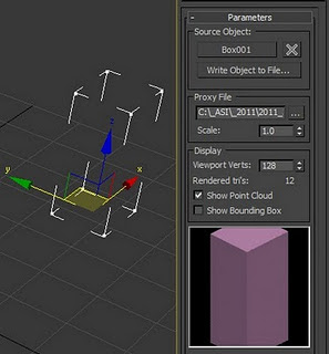
Need a stand-in for your objects? This can help save time for rendering and when working in a scene file. What is it? mentalray Proxies in 3ds Max. They are a placeholders that are only loaded into memory and are processed per bucket during rendering. Files that used to lock up or freeze should now render quickly!

Go to the Create Panel , select "mental ray" in the Primitives drop down. Pick the "mr Proxy" button and place a box in the scene. Go to "Modify" panel and pick the "none" button to select the source object in the scene. Then pick the "Write Object to File..." button to save the data of the object for rendering time. At this point everything is in place. Now you can copy, clone, or array the Proxy in your scene. You will see several boxes, but when you render they will all be nice rendered copies of the source object.

BIM, CAD, Revit and Commerical Interior Design

Many argue that BIM requires all work be done in a BIM authoring tool, like Revit. BIM does not exclude the incorporation of legacy data that exists world wide. In fact, for BIM to evolve the AEC industry it has to accomodate decades of hand drawn and CAD produced documentation. Does this information have the ability to contain and share the same volume of information and capability that a Revit model does? Absolutely not, however, legacy data provides valuable historical and as-built records that are useful for informing the design team while they create and/or re-create all or part of a project in Revit.

I suggest that there is far more renovation, remodel and addition work and less new construction. There is far more built environment than under construction. BIM is well positioned for new design, construction and operations where as much of interior design works in previously occupied space. Most of that space was not designed using BIM in its modern context. It only makes sense that to use Revit for commerical interior design, a designer must consider leveraging existing electronic files as part of the design or to build on top of. Until BIM is fully adopted in the AEC industry and all existing space and architecture is recreated using BIM authoring tools, it is logical to use CAD files as part of a BIM workflow.

Most fees do not have the capacity to re-model an entire facility or space for a renovation project. When the technology advances to streamline the 3D laser scanning to Revit model workflow and reduce the cost, then designers will opt for this path. So, for the near future, leverage scans of hand drawn drawings or CAD files in your Revit project to leverage the best of both worlds and available legacy information.