January 26, 2012

AutoCAD Text Height AUTOMATICALLY!

What is Annotative Scaling? Annotative scaling gives users the ability to place text one time in a drawing and have AutoCAD AUTOMATICALLY calculate text height at different scales. If you need to show a room name at 1/4" scale and 1/8" scale, there is no need for you to enter the text twice at two different text heights and on two different layers. With this one example, I reduced the time and number of AutoCAD text objects and layers by 50% using Annotative Scaling. In the image to the right, it is important to understand there are three button used for Annotative Scaling.
The first is the plot scale. This controls the size of any annotative objects like text, dimensions, blocks, and hatching.
The next button controls if you see ANY text for the current scale. This button is tricky. What it will do is show you the text that was put in at the original scale if you don’t have text at the current scale. If this button is off, you won't see any text if it doesn't exist for that scale.
Obviously, we want the text at the current scale not at the original scale. That's were the last button is used. If you toggle on this last button, AutoCAD will automatically scale text to the current scale.
If you’re still a little confused what should be on and what off, I tell people to toggle on both buttons. Place some text, change the Annotation Scale. and watch what happens!
Mark Petrucci


January 25, 2012

A Point Out Of The Cloud

Point Cloud Feature Extraction for Civil 3D provides versatile tools to facilitate the processing of point
cloud data. This plug-in includes four main features specifically for Civil3D users as following:

-Point cloud classification
-Ground surface creation
-Point cloud segmentation
-Road feature extraction

Wow! It also adds two new features! Extracting plane boundary as polyline and Export point Cloud objects to PCG files.

The options are quite the same as the release of Shape Extraction for AutoCad but Remember! The big difference is the Polyline option of the Boundary. . .


Now let's creat a Surface Model, and always estimate Tile and Grid size for performance.
Another download and add-on for Civil 3D. . . What more can we Ask For? How about an Easy Button?


Kenneth L. Driscol

January 24, 2012

Point Cloud Feature Extraction for Revit

Autodesk Labs has a new tool available to assist working with point clouds in Revit.  


Point Cloud Feature Extraction for Autodesk® Revit® 2012 software is a free* technology preview that allows you to work with point cloud more easily in Revit. This plug-in automatically extracts useful geometry features from point cloud of buildings and creates basic Revit elements to aid the building modeling in Revit.


WHAT TOOLS DOES POINT CLOUD FEATURE EXTRACTION PLUG-IN FOR REVIT PROVIDE?

Point Cloud Feature Extraction for Autodesk Revit 2012 provides the following tools to facilitate the point cloud editing after it is inserted into Revit:
  • Crop / Uncrop: Temporarily hide the points outside a rectangle or polygon
  • Hide Point Cloud: Temporarily hide the whole point cloud object to facilitate the inspection of the feature extraction result
  • Adjust Axis: Transform the point cloud data so that floor can be aligned with XY plane and major walls are parallel to Z axis
Moreover, this plug-in includes some main features specifically for Revit so that the extracted features / geometry can be smoothly integrated into the BIM workflow:
  • Datum Extraction: Extract both level and orthogonal grid
  • Site Extraction: Extract both terrain surface for ground surface creation and building footprint on terrain surface for building pad generation
  • Wall Extraction: Extract both straight wall layout and arc wall
  • Floor Extraction: Extract floor from selected points on the floor plan level

Starbucks Now Served in a Cargo Container

From the marketing front: Not so much a story about Applied, but I was really intrigued by this post on Starbucks reuse of shipping containers. Interesting from a re-use/re-cycle standpoint, but also from a design stand point as well. Click here to see the story. Enjoy!

January 23, 2012

Volumes with Cloud Optimization

I just optimized and minimized the construction cost of a 5 mile road in 20 seconds!

Cloud this and cloud that . . . Just kidding, but you should check out the New Vertical Profile Optimization on the Cloud with Civil 3D! Think about this:

The geometric design of a road is a crucial part in any highway construction project. Once fixed, the design determines largely the construction costs.
An optimal vertical road profile, with respect to earthwork cost, follows the ground surface as close as possible. The closer the road is to the ground profile, the fewer earthwork needs to be done in order to cut or fill sections of the road. However, due to design constraints like slope, grade changes, vertical curve length, etc., it is not always possible to follow the ground surface. Finding the road profile that minimizes the construction costs subject to design constraints is a process that we call profile design optimization. Traditionally, the design of road profiles is done manually by engineers using a
mass-diagram. In this approach, the vertical profile is evaluated with an integration of the earthwork volumes between the road profile and the ground surface.
The integral can be plotted by hand or with the help of software. After visual inspection of the mass diagram, the engineer changes the profile and re-computes the volumes. This process is repeated until a satisfying solution is found.

There are several disadvantages using the mass-diagram approach:

  • The mass diagram does not provide a real cost for a given design.
  • The mass diagram considers uni-directional earthwork only. It does not account for earthwork that could start on either end of the road.
  • The mass diagram does not account for different costs, such as excavation, embankment, load, borrow, and waste.
  • The mass diagram cannot combine multiple surface layers in combination with cut and fills.
  • The mass-diagram approach is a manual approach that is not able to incorporate design constraints automatically.
  • Due to timely and budgetary constraints, a final alignment is often chosen from a small selection of possible solutions. 

In the cloud-based vertical profile optimization, they address all the above shortcomings of the mass diagram with a new Cloud-based algorithm. To access this service, the user needs to use the Profile Optimization Wizard, which comes as a Civil 3D extension. Lets take a look.....

Where do you go for Autodesk related news and support?

I continue to be amazed at the speed and quality of information that is out there in relation to Autodesk. Whether it's a new release from Autodesk Labs, a YouTube video on using Inventor's Frame Generator, or a podcasted Autodesk University class (complete with downloadable PDF syllabi), you can learn so much, yet feel so overwhelmed.

Lately, Twitter has proven to be the most accessible (and controllable) stream of data I've found for tracking new technology and trends within the Autodesk family. You pick and choose who you subscribe to, and as a hybrid Autodesk Manufacturing and Plant news junkie, here are a few Tweeters I'd recommend following -


Autodesk Labs Scott (@scottsh115 ) - Scott Sheppard is the Program Manager for Autodesk Labs, and when new technology is hatched in the lab, he's the first to announce it.

Autodesk Inventor (@InventorTips) - chock full of tips, tricks and news related to Inventor.

AutoCAD Exchange (@ACADExchange) - features an "AutoCAD Expert of The Week" and requests questions for them to answer. There's also an AutoCADPlantExchange (@PlantExchange) twitter page with Plant related news too.

And of course, if you follow me (@TFiteASTI), you can get a smattering of (what I see) as the "greatest hits" from each of these and many more in the tweetsphere.


If you prefer interactive blogs hosted or moderated by Autodesk experts, take a look at all of the Autodesk Blogs that are available (http://usa.autodesk.com/adsk/servlet/index?id=4805213&siteID=123112) - this is a great point of entry into the Autodesk blogosphere. I've often found content there that has proven useful for answering tech support questions for my clients.

And when comes down to digging in to the software for "how do I do ____" questions, or confirming functionality within Autodesk products, try the Autodesk Wiki site, located at http://wikihelp.autodesk.com/enu.


January 20, 2012

HOLD Up! Do We All Need To BIM?

How can civil engineers more easily predict the outcome of their projects before they are built?  How do you create coordinated, reliable design information, while being able to respond to changes faster? How do you optimize designs with analysis, simulation, visualization, and deliver higher quality construction documentation? Starting with surveying and all the way through to supporting construction processes. . .

Look into this article that I created. . .

http://www.asti.com/Resource Library/Articles/Time_to_BIM_7-1.pdf


Kenneth L. Driscol

January 19, 2012

EXPLETIVE!! Can’t open AUTOCAD! Getting license error!

Occasionally that will be screamed throughout an office due to the end user getting an error when trying to open their Autodesk program. It can be extremely frustrating trying to figure out what could be the problem. Below is a list of the most common error messages and possible fixes for them.

(-00.00.00) – This is a popular one with the new 2012 software. There are typically 2 reasons this is occurring. Fist, a firewall is blocking access to the clients hitting the server. There are some ports that need to be opened, 27000-27009 and 2080. Another possible solution has to do with IPv6 being used on the server, either disable IPv6 if your office is not using it, or download and install the Autodesk Network License Manager IPv6.

(-4.xx.xxx) – This one simply means that the office has run out of licenses and the end user will either have to wait for a license to open up or someone will have to get kicked out of the software.

(-5.xx.xx) – This happens quite a bit when an office installed a software package with the incorrect product key, typically happens with the basic AutodCAD verticals. Solution is to uninstall/reinstall with the correct product key. The error message means that the feature cannot be found, or the product can’t be found in your license file.

(-14.xx.xxx) – This indicates that a problem occurred with the product finding the HOST NAME of the server, typically there is a possible problem with DNS on the network. If this was working and then stopped working, there might be a corrupt cascadeinfo file. See below on how to fix that.


(-15.xx.xxx) – This means that the server might be down. Verify that the services adskflex.exe and lmgrd.exe are running on the server. If they are not, open Autodesk Network License Manager (LMTools) and click on the start/stop/reread tab and then click on start server. To make sure they stay started, even after a restart of the server, click on config services tab and make sure start server at power up and use services are both checked, and then click on save service. This error can also be caused by the cascadeinfo file being corrupted. See below for fix.

(-18.xx.xxx) – License server does not support this feature. Typically this occurs when an office upgrades their license file to the latest version, but did not upgrade Autodesk Network License Manager. Install the latest version of ADLM.

There are many more error codes than those listed, check out http://forums.autodesk.com/t5/Installation-Licensing/FlexLM-Error-Code-Chart/m-p/1438943 for a complete list.

Corrupted cascadeinfo.cas file needs to be deleted. It can be found in the following locations:
Windows XP:
C:\Documents and Settings\All Users\Application Data\Autodesk\Adlm
Windows Vista and Windows 7:
C:\ProgramData\Autodesk\Adlm

Autodesk apps – business and pleasure?


Autodesk has introduced several new apps over the past months, and will likely continue to do so. This blog has shared and explained those apps with you like Design Review and ForceEffect.

Here is a quick breakdown in no particular order, of the other Autodesk ipad, iphone and android apps, some of them for business and others for pleasure…
Pixlr-o-matic – A fun tool for editing pictures, adding effects, flares, tints, and that vintage look.
Fluid FX – Special effect for your pictures. Pinch, pull, and distort
Inventor Publisher Mobile – Interact with 3d assemblies from Inventor
AutoCAD WS – DWGs on the go. Open, revise, measure, and notate. You dont have to be an AutoCAD expert to pick up on this little app.
SketchBook Express – Access project documents and designs securely from anywhere. View DWF files – 2d and 3d. Upload photos and files to the Buzzsaw cloud. Sketch a design onsite, upload it to the cloud to share and collaborate with others.
123dSculpt - Digital clay model sculpting. Create unique designs by shaping and molding objects in the computer.
Learn more about these apps, and others on the Autodesks app website: http://usa.autodesk.com/adsk/servlet/pc/index?siteID=123112&id=16953811

January 16, 2012

Just AutoCAD can do BOM

While at a client meeting last week, my client asked if AutoCAD can create a Bill of Materials. As soon as I heard the question, my first reaction was to write a blog. While he knew it could, he had not done it before. I answered his question but that wasn't my first reaction! I explained to create a BOM, you will need blocks with attributes. Long time AutoCAD users are now thinking of the old ATTEXT command. If you are, stop it. We always had the ability to create a BOM with ATTEXT but there's a better way. Using AutoCAD 2012 and its TABLE command, you can generate a quick and easy BOM. However, don't forget you will need blocks with attributes. After all, what is a BOM? It's a list of parts (blocks) and data (attributes) associated with the parts.

Below is an AutoCAD control wiring diagram with many blocks and attributes. The image on the left is an enlarged view of the BOM I generated in seconds, not minutes. It took longer to write this short blog than it took to create the BOM! Can AutoCAD create a BOM? I have two responses, yes, and it's easy.

Mark Petrucci

Design Review Mobile App

There was a time when I can remember preparing for a meeting or even going to the plant to discuss design and engineering issues with multiple detailed drawings in my hands and needing someone to aid me in opening doors. However, with today's technology, the burden of lugging around loads of documentation is becoming a thing of the past. With more and more people starting to make the move to mobile devices and discovering the vast world of apps available, I would like to point out one specifically which allows you to view, markup, and annotate 2D and 3D DWF files from your Autodesk Cloud account. It is the Design Review mobile app by Autodesk, Inc. and it is available for the following devices: iPhone 3GS or higher, iPad 1 or 2, iPod Touch 3rd generation or higher, with a minimum operating system of the Apple iOS 3.2.


Links for Referenced Material:

 
-Jason Miles

January 12, 2012

Show off Showcase

What is this thing we call Autodesk Showcase? It's a real-time 3D presentation program and a rendering program. It does not replace 3DS MAX. While you can create some pretty amazing videos with 3DS MAX, you can get pretty close with Showcase. The advantage of Showcase is the learning curve. 3DS MAX is geared more for the entertainment industry while Showcase is more suited for AEC. See my video below. All objects were created in AutoCAD. Materials and animations were done in Showcase. No other software was used. There is a lot more we can do with Showcase. Please let me know if you'd like to see more Showcase videos.
Mark Petrucci

January 10, 2012

Breaking up isn’t hard to do: Revit MEP

In the past I have had to help several clients clean-up, break-up, and troubleshoot Revit models. With my focus being on RMEP, this entry will be from that point of view.

Breakup by Discipline

The process to break up a Revit model is about the opposite as to what we would do in AutoCAD. AutoCAD has a WBLOCK command; Revit does not.  

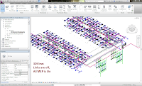
So, take any RMEP model, we will call it ABC_RMEP.RVT, that contains all disciplines. Open the model, SaveAS, for example: ABC_PLUMBING. Now the fun begins. I will make a 3D view and then using the Visibility Graphics, I will turn off all the objects related to Plumbing.

You may ask now, what about pipe? Depends, do you want to have only the Plumbing Pipe in the Plumbing model? If so, then use a FILTER that will sort out the Plumbing Pipe, leaving the Mechanical/Hydronic Pipe “on” for selection/deletion.


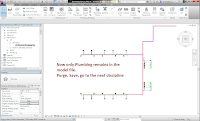
Once the other disciplines have been deleted, issue the PURGE command and selectively remove anything that isn’t Plumbing in nature. Save the file again. Lather, rinse, repeat for the remaining disciplines.Once all the discipline specific files have been created, return to each model file and link in the other discipline files, if needed.


This scenario lends itself to maintaining the SHEET views in each discipline’s specific model file. Alternatively, a Centralized model could be maintained that links in all the disciplines and is used specifically for SHEET views, which then would have all the SHEETs in a single file.


Breakup Troubleshooting
In the past I have had to break-up a Revit model to determine where a problem is that is affecting the overall performance of the model. Performance issues that I have run into in the past: 1) Pick a point to place a pipe, wait…wait…wait… After too much time passing, the point finally registers; 2) Zooms and Pans anomalies, for example, the view just plain won’t do it; 3) printing oddities; 4) and I am sure there are others.

In this case, I will use a plumbing example. Similar in steps to the “Breakup by Discipline”, isolate out the Plumbing model. Once saved, run Purge to clean out anything NOT plumbing and save again. Next check the performance problem. If the problem persists, create a 3D view for troubleshooting purposes. Make sure everything is on, no filters overrides, etc. Then, what I do, is first: DELETE EVERYTHING. Wow, sounds radical, but this lets me do a performance test to see if it is anything is in the model causing the problem. After deleting everything, if performance goes back up, then that tells me the problem is related to the model itself and not some other issue. Next, I will reopen the troubleshooting model, create a 3D view, and then go to a TOP view via the ViewCube. Now the fun again, follow a process of deleting a little and test performance, delete a little and test performance. Eventually, if all goes according to plan, you will delete a little and the performance problem will go away. REMEMBER the area you deleted, close without saving the file, reopen the full file again, and delete just the little bit that resolved the problem and test performance.

I have had situations where I had to delete two little areas, so this troubleshooting process can be a challenge sometimes.

ADDENDUM: Jan 12
Thumbs up to Steve Stafford: http://revitoped.blogspot.com/2012/01/revit-has-wblock-feature-too.html
Steve makes a valid comparison about SaveAsGroup being similar to WBLOCK from AutoCAD. The catch for me is the results of the group save.  My experiments left me with alot more work to do with the group versus the delete/saveas process.  My testing was with a plumbing model that was systemized with a single Cold, single Hot, and single Sanitary system. and all were well connected.  The result however, put every pipe, fitting and fixture onto it's own system.  I lost all my template settings except those directly related to the objects in the group (no filters, no view templates, etc).  So, I thought to link, bind, ungroup into a template and I discovered it made an even bigger mess of my pipe systems, connections were lost, but alignment was perfect.  I agree 100% with Steve's comment, "Regardless the hard part isn't Save as...it's carefully filtering/selecting everything."  Steve also says, "SaveAsGroup could/would/should work", and  again I agree 100% that it 'should', but like many features in Revit, maybe it does nicely for Revit Architecture, but in this instance it doesn't work too well for RMEP.  And again, thank you Steve for referencing us.  It's these types of conversations that make writing this stuff worthwhile.


dennis

January 7, 2012

3D Design and 3D Printing - The Future is Now


For years Autodesk has used catch phrases like "Digital Prototyping" and "Experience Your Ideas Before They're Real" to convey the concept that earlier validation and sign-off on designs can reduce errors, increase throughput, and shorten development cycles.

Early adopters of this concept realized that expressing a design through a 3D model provided the opportunity for differentiation in competitive markets from those who merely provided a pretty picture, or 2D drawings replete with layers of uninterpretable linework. The BIG benefits for companies using 3D (after winning a project) could also include higher margins on projects, shorter time to market, and a reduction in the "gotchas" of unforeseen interferences/clashes within assemblies and field failures later.

So when going about the process of creating new, previously unproven designs, seeing it in 3D is nice, but to the consumer, machinist or builder, the 3D proof is in the printed pudding. The big hurdles in generating a conceptual model have always been the tying up of expensive machinery, manpower and material costs, when in reality, the end user may simply need to get the idea of how a product would look and feel.

As with most developing technologies, cost has been the driving force preventing widespread adoption. While SLA (Stereolithography) 3D printing has been around for over 25 years, it has traditionally been so expensive that companies would outsource 3D parts and generate scaled physical models only when requested by a customer or if necessary to win work. However, 3D printing has finally reached a point where quality and affordability have converged - we're now in the age of desktop 3D printing....

A desktop unit such as the 3DTouch from 3D Systems (link below), uses thermoplastics to heat the material through the extruder (or print head). The extruder then pushes out a very fine plastic thread which is applied layer by layer according to x and y coordinates, building a solid, 3D object, right before your eyes. And with the low cost of these systems, when coupled with 3D modeling software (like Inventor or Solidworks), the point of entry into conceiving, designing, testing and digitally/physically prototyping a design is now achievable for under $10,000.


Still think 3D printing isn't ready for prime time? A recent article on CNET.com (link below) suggests that 2012 could be the year that a "company like FedEx Kinko's will start offering 3D printing as a consumer-level service."

Imagine that - coming up with a design, uploading it to the Kinko's website, then picking up the part a few hours later. It seems that the harmonic convergence of mainstream 3D Design and 3D Printing has now been achieved.

Links:

CNET article - http://news.cnet.com/8301-13772_3-57345836-52/culture-five-predictions-for-2012/

3D Systems printers - http://www.asti.com/Products/Item.asp?Mkt=Com&ProductID=3D_systems&SolutionID=All

January 6, 2012

Quadrifying Objects

No, I did not make that word up.  It is a tool within 3ds Max Design for simplifying geometry from unnecessary faces, which could possibly be triangulated elements, to reduce the faces of an object. Or in other words: a tool for converting triangles to quadrilaterals. Using this tool could be important to reduce rendering times of scenes where a flat surface doesn’t need all of the faces and verticies.

After converting the object to an editable mesh. Go to the Graphite Modeling Tools tab, and then to Geometry (All) panel and click on the dropdown arrow to display the Quadrifying options. Choices include Quadrifying All, Selection, Edges, and Edges from Selection.

Hold and Fetch

Hold and Fetch within the realm of 3ds Max Design is used for placing a timestamp "Hold" in your scene, which can be retrieved "Fetch" at a later point down the road in your scene. This includes cameras, lighting, viewport configs, geometry and selections sets.

You can only Hold/Fetch to one point in your scene, and if you Hold for a new point your previous Hold is lost. Hold is a useful tool when exploring different design ideas or work that may not be saved. Be advised Fetch dumps all operations in the Undo/Redo history list.

See a short video on Hold/Fetch in action: Hold-Fetch

January 5, 2012

Why BIM? . . . Again?

I was recently asked by one of my sales people to craft a quick overview of BIM trends that would make someone want to use it.  I had a couple of gut reactions and some realizations:

Gut Reaction 1:  I am over it.  Do we still have to have this discussion?  It's a five-year-old question.

Gut Reaction 2:  The industry is past it.  The talking heads are now arguing about what is after BIM and are coming up with ridiculous things like "BIM 2.0" and 7D, 8D, 9D and XD models.  (How many dimensions can there be?  This isn't quantum physics, people.  I'm going to create a String-BIM theory just for my own amusement.)

Realization 1:  The industry is NOT past it.  While we now have the talking heads dithering about "BIM 3.0" and 99D models, we still have parts of the country and world where BIM is VERY NEW.  We still have owners that have no idea why they should (or should not) be using it.  There is no NEXT BIM.  There is only refining it and building upon the idea to make it better.

Realization 2:  I am NOT over it.  I am over BIM, the singular, "solve anything" application.  But not over BIM as a team based, data rich set of processes that can help solve many relevant industry problems. While my frosted side wants to dance and splash in new discoveries and uses for BIM data, my crunchy, wheat-y side realizes that we still need to evangelize, but differently than we used to talk about it; with more understanding, foresight and relevance.

The following is my initial response to this request.  It needs some additional word-smithing, and doesn't go very deep at all, but I think this is the basis of what the next generation of BIM adopters needs to understand to get on board and quickly catch up or even innovate upon current understanding.  Based on what we have seen, each new wave of adoption is better than the last.  We shouldn't dismiss these later waves of BIM adopters, but realize that their new energy in learning applications that have had immense amounts of additional development could make them better than early adopters whose skills and BIM usage may have hit a plateau.  These later waves also have something that the early adopters didn't have - the backing and desire of a more educated client to do better:

"BIM isn't the trend anymore.  To be quite frank, we are past that.  The real drivers towards BIM adoption now are synergistic uses that go above and beyond simply having a 3D model of a building that we can collide.  The current BIM catchwords are really focused on modern operational and economic issues that are the true underlying issues that BIM can help to solve. 
  • Efficiency:  Let's be honest: The economy is still in the dumper.  There are some bright spots, but let's not get too excited because it will never be the same.  The construction industry loses a massive amount of money every year to wasted effort and time, not to mention materials.  Some estimates are as high as 40% of profits are lost to lack of efficiency.  This is unforgivable – even in the best of times.  BIM, due to the nature of being able to view, quantify, and share helps eliminate over-purchasing and rework in all phases of the building life cycle.  Additional ability to visualize construction sequencing helps ensure timely and safe construction of the building.
  • Sustainability / Energy Analysis:  Green design is about data – Calculations, weights, locations, volumes, etc.  BIM, with its ability to tie that information to 3D geometry (which is just now really being harnessed by design teams) can provide a powerful synergistic relationship for providing sustainable design and analysis.  This data can also be used further downstream by owners (See FM / O&M).
  • Partnering/Integrated Processes:  The ability to share project data and design concepts is not new to CAD software, but the ability to more clearly see design decisions, data and analyze their effects is compelling in many ways.  From the designers to fabricators to owners, the entire project team can be involved in ways that are heretofore unprecedented.
  • Facility Management / Operations & Maintenance:  If an owner has a clear understanding of Facility needs, the BIM can be the backbone of a strong FM / O&M initiative.  What better place to tie the data to than a virtual model of a building or campus?  Things such as manuals, maintenance schedules, real time energy monitoring, asset management, space allocation can all be tied to a BIM and vice versa.  The industry is just now beginning to really see the need for "portals" to tie all of this data together for greater operational efficiency and knowledge.  This is the stuff of science fiction that is happening now.  
  • Standardization:   BIM has the capability to standardize . . . . everything.  Several large companies from Starbucks to Target are standardizing on BIM.  Giving them an edge over competition with some of the FM uses above, but also the ability to visualize remodeling, signage, displays, etc.  The industry as a whole would benefit from manufacturers creating standardized BIM models of everything from tables to pumps to furniture that will contain all the data needed for purchasing, quantities, LEED and much more.
These things are synergistically tied to each other as well.  Solving one issue tends to solve the others. BIM is not THE THING, but a tool that helps foster greater understanding and solutions to the real problems listed above and more.  In our own experience we are training BIM tools at a 4:1 rate over traditional CAD applications.  The classes are getting more specific and targeted on a weekly basis.  Additionally, we are now working with owners in commercial, educational, and government spaces helping them craft their own BIM requirements and corporate BIM Execution Plans – which is possibly the real trend.  BIM isn't about marketing brochures or colliding 3D pieces anymore.  Owners are starting to understand how it can help them generate efficiency, design sustainably, foster partnering, standardize data, trim operational costs and reveal new understanding about how they use their spaces.  Now that I think about it, that's not a trend, that's finally getting it right." 

-Pete Zyskowski

Project Storm


In a previous blog post I mentioned using Project Storm from Autodesk Labs. Let me explain a little about this lab preview technology. In short it is: Cloud based structural analysis. Engineers can run analysis on their models in the cloud and the results visualized in Revit Structure. Disruptions to engineers workflows are minimized by using Project Storm in the cloud as the design continues to evolve.

Useful reports can also be generated to review the analysis results.

Addition functions include:
  • Defined
  • Analysis profiles
  • Easier user interface
  • Analysis step by step walk through

Here is a link to more information about Project Storm:http://labs.autodesk.com/utilities/revit_storm/

January 4, 2012

2D to 3D Tool for Inventor

A common question that I get from clients that are transitioning from AutoCAD to Inventor is, "Will I be able to use our 2D CAD part drawings within Inventor?" The answer is yes! This is possible with the 2D to 3D Tool. Not only is this possible, but it will also save you time in the long run by not having to create the part from scratch. First, you must download and install the 2D to 3D Tool from Autodesk Labs. With an empty part file (.ipt) or by having an active empty part in the assembly context, follow these simple steps:

1. On the Sketch tab under the Insert panel, click on ACAD
2. Choose .dwg file, click Open

3. In the Layers and Objects Import Options dialogue box, uncheck select all, choose the desired geometry, click Next

4. In the Import Destination Options dialogue box, ensure that the Constrain End Points box is checked, click Finish, and click Finish Sketch

5. Under the Model tab within the 2D to 3D panel, click on Base View
6. Select the face for your base view on the three dimensional cube shown in the graphics window

7. Select the sketch segments that define the base view and click Ok


8. Under the Model tab within the 2D to 3D panel, click on Projected View
9. Select the sketch segments that define the projected view and click Ok

10. Utilize the Create feature options under the Model tab to create the desired part


- Jason Miles

May the "ForceEffect" be with you


Autodesk seems to be pushing out new (and FREE) tools every week or so, many of which are mobile apps for iPhone and iPad users. While catching up on emails in the manufacturing lounge at Autodesk University this year, I was fortunate enough to sit down with Andrew Sears (Solutions Engineer, Autodesk) who provided me with an inpromptu demo of ForceEffect, a free app that allows engineers to draw, constrain and simulate concepts using free body diagrams by simply tapping objects to select, move, rotate and scale.

It's very easy to create free-body diagrams and generate dimensionally correct elements - you use familiar iPhone/iPad motions to sketch and snap to other elements on the sketch. In addition, you can also bring in a photo as a background for either modifying existing designs or creating new ones. Once you've placed your elements, you apply forces, unknown forces or moments and then add supports such as sliding pins, fixed pins, grounded, fixed or welded.

Sketch geometry can be moved, re-sized, deleted and dimensions can be edited simply by tapping the dimension value and entering the size you require. Autodesk ForceEffect also generates a report that can be printed, emailed or viewed using any Web browser. In addition, export capabilities enable easy workflow continuation in any CAD application by emailing and exporting the sketch to a DXF file that can be reused in tools like AutoCAD Mechanical and Autodesk Inventor.

You can download ForceEffect from the Appled iTunes store here - http://itunes.apple.com/us/app/autodesk-forceeffect/id476321600?ls=1&mt=8

January 3, 2012

a la carte rendering

For 3ds Max Design software users who are new to the world of rendering, there are several options to choose from. At first glance in using the software you have to choose what “type” of rendering process you are going to use… the default Scanline renderer or mental ray which many folks refer to as “bucket rendering”. It is known as bucket rendering because the computer processor or multiple processors work on renderings one square area at a time, verses the scanline rendering which is a pixel row, starting from the top one row at a time.
The image below shows the rendering in progress. 3ds Max Design will render a low level quality pass over the scene, which looks pixelated or like mosaic tiles. This is to help you determine the camera shot, angle, and if the scene is the correct one. This quick pass allows you to cancel the rendering, and not have to wait several minutes for a non-desired rendering.
The next image shows additional progress on the rendering. The front of the car is complete, and the black box by the front fender is the processor working on refining that area. If you have a multi-core processor computer, you will see several boxes jumping around the scene working to refine the areas.

And if you are wondering, the image at the top took 35 seconds to render. It would of taken double that with scanline and the quality wouldnt of been as nice. Overall mental ray rendering will give you more realistic renderings, with faster results. It is the preferred industry standard/method of rendering. But, you can switch between scanline or mental ray. Either choice can be set in the Custom UI and Default Switcher in 3ds Max Design. A restart of 3ds Max Design will be required.
But that is just the first of many choices for rendering methods. Check back for future entries on renderings and 3ds Max Design. Until then... Happy modeling and rendering!

Structure Generator


Autodesk Labs introduced Project Structure Generator for Revit Architecture and Structure. This preview technology provides a connection between conceptual massing models and the physical objects created during the design process. The Structure Generator allows designers, architects and engineers to visualize their design at the earliest stages. This includes the physical and analytical model.

Some other useful tools include:
  • Volume and weight predictions of materials
  • Create variations of the design and display them as needed.
  • Static analysis via Project Storm or Robot Structural Analysis
To find out more, here is a link to the Project Structure Generator on Autodesk Labs: http://labs.autodesk.com/utilities/revit_structure_generator/